[作りモノ] カテゴリの記事
全211件 (211件中 1-50件目)
-

リビングの整理棚を組み立てた
今日は晴れて暑かった。気温は25度を超えてたんとちゃうかな。風があったので、体感的にはちょうどよかったのですが...---リビングの整理棚にモノを結構入れてるので、経年劣化で歪んできてました。稼働棚を支えるポストが歪のせいで緩んできて棚が落ちそうになってました。っちゅうことで、こないだ某ワンクリックなとこで組み立て式の整理棚を確保しました。連休に入って、子ども(弐)が家にいる今日、組み立てることにしました。組み立ては説明書通りに行えば、特に問題はないのですが、上下や裏表の間違い、部品番号の間違いなどに注意しながら子ども(弐)と作業してたら結構組み立てに時間がかかりました。木ダボを使うので木工用接着剤が必要なのですが、組み立て途中で付属の接着剤が無くなってしまったので、近所のホームセンターに買いに行く、っちゅうハプニングもありました。(^^;扉の蝶番を取り付けるときに木ネジが留めにくかったのを除くと、概ね部品の加工精度はよく、組み立てやすい整理棚ではありました。組み立てた整理棚整理棚を組み立てた後、元の整理棚からモノを出しつつ整理して、新しい整理棚に格納するのにかなり時間がかかりました。今日は嫁はんがいなかったので、嫁はんのモノとかあると保留、っちゅうことになって、片付かない、っちゅうのもありました。大体整理棚の中身の移動は終わったので、今日は一段落です。古い整理棚は分解がめんどくさそうなので、粗大ごみとして回収してもらわないといかんのでしょうが、そのやり方を調べなければ... (^^;;--- 20:20 ---
April 28, 2024
コメント(0)
-
ワイヤレスイヤホンを修理した
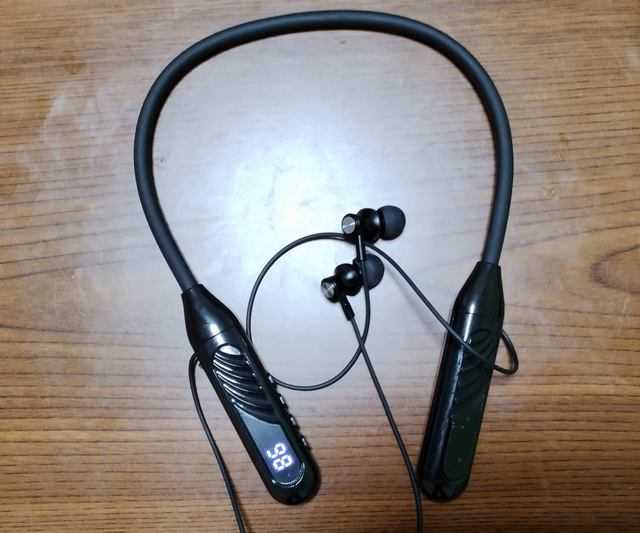
今日は早めで帰宅は18時過ぎ。某通販で確保したワイヤレスイヤホンですが、電源は入るものの左のイヤホンから音が出ない、っちゅう不具合がありました。電源は入るのだが...考えられる原因は次の4つです。(1) 右側筐体の制御基板からの線が断線している(2) 左側筐体のイヤホン接続部が断線している(3) 左側イヤホンの内部で断線している(4) 右と左をつなぐチューブの中で断線しているこのうち(4)の場合は可逆的に直しようがないので諦めるとして、まずは(1)、(2)をチェックするために左右の筐体を分解してみました。分解した筐体右側筐体には制御基板、左側筐体にはバッテリが入っていました。まずは左側筐体内の配線を調べて制御基板へ来てる音声信号ラインを特定しました。そのラインをテスタであたってみましたが、導通していました。左側筐体のイヤホン接続部もテスタであたってみましたが、こちらも断線していませんでした。残るは左側イヤホン内部。イヤホンの殻割は割とめんどくさかったです。(^^;左側イヤホン内部こちらも断線してなさそうやったのですが、イヤホン内部のスピーカへの配線が何だか怪しかったので、再半田してみました。すると、これが正解やったようで、左側イヤホンからも音が出るようになりました。っちゅうことで、左側イヤホン内部の半田不良が音の出ない原因だったようです。このイヤホン、バッテリ容量が大きそうで音もそんなに悪くないので、使い道はありそうです。--- 18:35 ---
April 23, 2024
コメント(0)
-
溶岩腕時計を修理(?)した
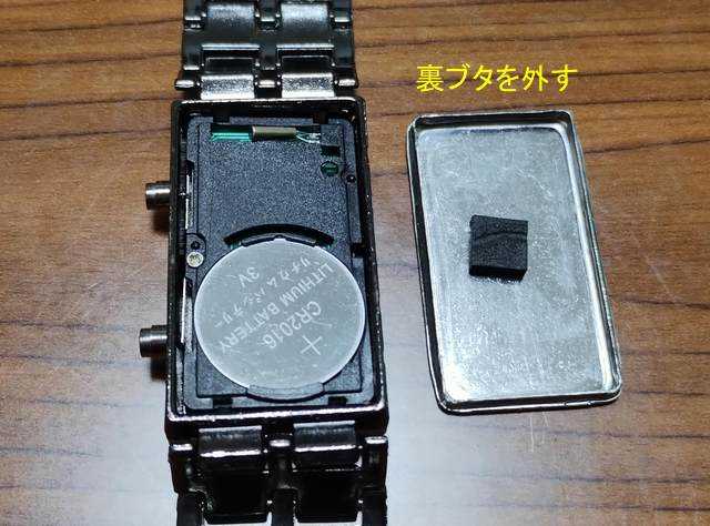
今日は晴れていい天気。今日も気温は上がりそうです。25度ぐらいまでいくのかな?---AliExpressで腕時計を3本買ったのですが、そのうち1本のデジタル時計(溶岩腕時計)の時刻合わせができない状態でした。時計裏面のカバーを外すと時計ユニットが取り外せそうやったので、修理してみることに。裏面のカバーを外す中国製品は加工精度が甘いことが多々ありますが、この裏面カバーについては勘合精度がよく、取り外すのに結構時間がかかりました。(^^; 電池は CR2016 で簡単に交換できそうです。時計ユニットが取り出せた時計ユニットは特にネジで留まってるわけではなく、筐体にはまっているだけでした。これを裏面カバーで押し付けて固定する感じなんでしょう。時計ユニットのスイッチ部分時計ユニットに部品としてのスイッチが付いてると思ってましたが、実際は基板側の端子におそらくGND接続された金属板が接触することでスイッチ動作する構造でした。確かに300円で売るにはコストダウンが必要ですからね。スイッチ部品をうまく削減しています。金属板を押すための棒では、スイッチ動作する金属板をどうやって基板側の端子と接触させるか、という点については物理的に棒で押す、という構造になっていました。外から見てボタンに見えるのは実はこの棒を押すための機構なのです。時刻合わせは下側のボタンで行うのですが、どうもこのボタンの棒でスイッチとなる金属板を押せなくなっているのが動作不良の原因のようです。とはいうものの、金属板は基板に固定されてるので、棒で押せるようにするには、微妙に曲げてやる必要がありました。これが結構難しくて、ピンセットで金属板を曲げようとして折ってしまうとダメなので、慎重に曲げる必要がありました。この状態で仮組して、上の表示切替ボタンも下の設定用ボタンも動作することを確認してから、裏面カバーを取り付けました。が、元のようにピッタリははまらなくて、少し角が浮いてるような感じになってしまいました。(^^;; ここで加工精度出すなら、内部のスイッチ機構ももっと加工精度出してほしいところです。(^^;;さて、もうひとつの問題点やった、バンドをどうはめるか、という点についても解決しました。片側の部品が開くようになっていた最初、固くて気づかなかったのですが、上図の部分が開くようになっており、これで対になる金属棒をはさみこむことでバンドをはめることができました。勘合が結構固いので、一度はめたら外せないのではないかと不安でしたが、そういうこともなく、バンドの付け外しができています。腕にはめてみたところ腕にはめてみましたが、ちょっとバンドが余る感じで、腕を振ると文字盤の面がぐるぐる腕の周りを回ります。でも、そんなに腕を動かさなければ割と安定してるので、バンドを詰めなくてもよさそうな感じです。人によっては、ゆるゆるだったり、きつきつだったりするかもしれませんが...実用的になった溶岩腕時計AliExpressから届いたときは不良品だった溶岩腕時計ですが、分解してちょっと調整するだけで復活することができました。分解修理の楽しみも与えてくれるとは、やっぱりみんな大好きアリエクですね。(^^;;--- 10:10 ---
April 13, 2024
コメント(0)
-
Nintendo Switch用プロコンのジョイスティックを交換した
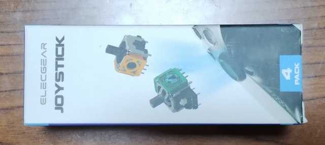
今日は晴れて温い。昨日と同様、春の気分です。---子ども(参)と嫁はんから、Nintendo Switch 用のプロコンのジョイスティックが勝手に動くのでスプラトゥーンができない、と言われてました。調べてみると、プロコンの交換用ジョイスティックが某ワンクリックなとこで売ってるし、交換方法を書いたページもあることが分かりました。っちゅうことで、交換用ジョイスティックを入手。交換用ジョイスティック4個入4個入で売ってたのですが、子ども(参)と嫁はんから修理依頼を受けたプロコンは2個あるので、ちょうどよい感じ。っちゅうことで、プロコンを分解してジョイスティックを交換していきます。プロコンには特殊ネジは使われておらず、+ドライバだけで分解できました。グリップ固定ネジを外す左右のグリップを固定しているネジを外してグリップを抜きます。バッテリカバー(?)を外すバッテリカバー(?)を留めている4か所のネジを外してカバーを外します。バッテリを外すバッテリを外します。その後、本体を2分割するために5か所のネジを外します。本体内部のケーブルを抜く本体を2分割するために開けていくのですが、内部に接続ケーブルがあるので注意して開けます。このケーブルはどちらか片側で抜いておきます。2分割した本体2分割するとこんな感じ。次に基板を留めてるネジを6か所外します。基板を留めてるネジを外すネジを外したら、赤○のネジで留まってる白い部品も外してしまいます。振動モータを外す左右の振動モータを外します。振動モータは割ときっちり両面テープで留まってるのである程度の力が必要です。が、振動モータ側の配線はフレキシブルケーブルにつながっているので、あまり強すぎると、このケーブルにダメージを与えるので、力加減が必要です。サブ基板のネジを外す基板を起こすとケーブル接続されたサブ基板が見えるので、サブ基板を留めてるネジを1本外します。これでようやく基板全体が外れます。基板の裏側基板の裏側です。ジョイスティックは結構なピン数で半田付けされています。この半田を吸取線で吸い取るのですが、一度追い半田(追加で半田を盛る)をしてから吸い取ると吸い取りやすいです。半田を吸い取ったらジョイスティックを外す全ピンの半田を吸い取ってピンとパターンの間に完全に隙間ができたら、基板裏からジョイスティックを押して外します。この後、パターンを無水アルコールできれいにしてから新しいジョイスティックを半田付けします。新しいジョイスティックを取り付けた新しいジョイスティックを取り付けたら、後は逆順で組み立てていきます。STEAMの設定から動作確認STEAMの設定の中にコントローラ設定があり、コントローラがつながっているとテストができます。プロコンもちゃんと認識してくれて、専用の動作確認画面で確認ができました。これは便利。ジョイスティックが勝手に入力される現象は解消しました。これで復活したプロコンが2つになり、対戦ゲーム等でも使えるようになりました。プロコンのジョイスティック交換は思ってたより簡単でした。半田を吸い取る地道な作業が必要ですが、面倒なのはそれだけで、半田付けできる人なら簡単に交換できます。交換用のジョイスティックも4個で1.5~2千円ぐらいで売られてるので、プロコンを買いなおすよりもだいぶ安く上がります。何かもう1台調子の悪いプロコンが自宅にあるらしいのですが、そちらは清掃だけで直るかも。っちゅうか、プロコンなんで3台もあるねん。(^^;--- 10:35 ---
March 31, 2024
コメント(0)
-
セルスタRで確保した謎ユニット
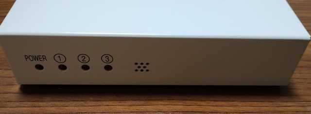
今日は早めで帰宅は18時過ぎ。昨日、セルスタRで Raspberry Pi B+ ver1.2 が入った謎ユニットを確保しました。前面側面背面前面には電源LEDと3つのLED、音出し用の穴があり、側面には Raspberry Pi のものと思われるHDMI端子とビデオ端子があり、背面にはRaspberry Pi のUSBとLAN、制御用の(?)RS-232C端子があります。これだけでは何に使うものかさっぱり分かりません。内部蓋を開けると、Raspberry Pi の基板と拡張用の基板があり、フラットケーブルで接続されています。SDカードは一旦Raspberry Pi を筐体から外さないと交換できないようです。っちゅうことで、元々の動作を確認したら適当なOSを入れて遊んでみようかと思います。--- 18:40 ---
March 25, 2024
コメント(0)
-
リモコンが来たけれど...
今日は在宅勤務。ダイニチ電子の地デジテレビWPT-H1100が映るようになったのですが、リモコンがないと何かと不自由なので、50社対応のリモコンを買ってみました。それが今日来たので試してみたのですが、うんともすんとも反応するメーカーコードがありません。(^^; 大体予想はしてたのですが...主要なマイナーメーカー(?)のコードでは全く反応なし。電源のオンオフさえできません。多少コードがずれてても電源のオンオフぐらいはできそうなものですが... もしかして、テレビ側の赤外線受光部が壊れてるとか?? (^^;;こうなったら0000から順にメーカーコード総当たりしてみるしかないのかな。時間のあるときにチャレンジしよう。--- 20:20 ---
December 12, 2023
コメント(0)
-
ジャンクで買ったダイニチ電子の地デジテレビWPT-H1100が映るようになった
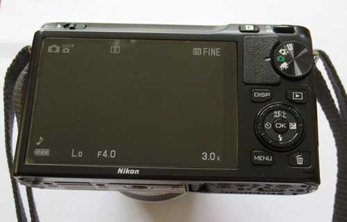
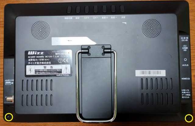
今日は早めで帰宅は18時。昨日、インバース横の店で確保したダイニチ電子の11.6インチHD地デジテレビ WPT-H1100ですが、ACアダプタ(12V 2A)をつないで電源を入れても電源LEDが光るだけで何も表示されませんでした。っちゅうことで、中身がどうなっているのか、開腹してみました。ネジ2本を外すネジ2本を外したら、ベゼルのところをペキペキと外していけば液晶側と本体側に分かれます。液晶ケーブルが挿さってなかった...本来はバッテリ内蔵でポータブルとして使えるようなのですが、バッテリはありませんでした。これは予想通り。あと、液晶ケーブルが外れてたのもほぼ予想通りですが、どこに挿すのかが分かりません... (^^; 基板はどうも一枚だけでチューナと信号処理が載ってるようです。この基板の裏側に気になる付箋「"入力信号なし"チューナー」が貼ってあるのですが、その近くに液晶コネクタのピン名らしきものが書いてあるのを発見。液晶コネクタのピン名?このピン名らしきものとコネクタの電源配線らしきものを照らし合わせて、基板表のヘッダピンに挿し込みました。合ってるのかなぁ... (^^;;液晶コネクタとバックライトケーブルを基板に挿した最悪液晶パネルが逝かれるかも??と思いつつ電源を入れてみると、液晶のバックライトが点灯し、Wizzのロゴが表示されました。これで合ってたみたいです。ひと安心。店でB-CASカード付で買ったので、B-CASカードを挿して、アンテナケーブルを接続すると自動でチャンネルスキャンが始まりました。仮組なんやけど... (^^;; とりあえずチャンネルスキャンが終わって、テレビが観られることを確認して基板を筐体にねじ止めして元通りに組み上げたのですが...ここで例の付箋の現象が発生しました。電源入れてTVモードになっても設定をロードせずに「入力信号なし」と表示されるのです。さっきはテレビが映ったのにおかしいなー、と色々ためしてみると、基板に載ってるチューナモジュール側のネジを締めるとこの現象がでることが分かりました。何でやねん!っちゅう感じですが、チューナモジュールにかかるテンションとかで微妙に変わるのかもしれません。テレビが映ることを確認して組み上げたのですが、また入力信号なしとなりました。どうも液晶ケーブルとアンテナケーブルが干渉してこの現象が起きてる風やったので、液晶ケーブルをアンテナケーブルと干渉しないように配線しなおして組み上げました。液晶ケーブルを配線しなおしたこれでようやく普通にテレビが映るようになりました。11.6インチのHDやからそれなりに見えるリビングにすぐに映るテレビがなかったので、WPT-H1100をリビング用のテレビにすることにしました。難点はリモコンが無いので、背面パネルで操作しないといけないことでしょうか。また、副音声が主音声と同時に流れる設定になってるのですが、リモコンからしかこれは設定できないような感じです。設定でメーカ変えられるリモコンを発注したので、合うメーカがあればいいか... という状態です。ダイニチ電子ってマイナーそうやから合うモードないかもね。(^^;;--- 20:10 ---
December 11, 2023
コメント(0)
-
KUMAN ISDS205A を Androidスマホで駆動した (Hscope)
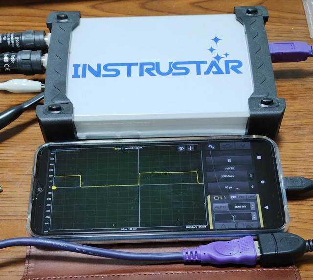
今日は在宅勤務。とある調べものをしてたついでに、USB オシロスコープ KUMAN ISDS205A をスマホアプリで駆動できることが分かりました。アプリはHscopeっちゅうもので、他のUSBオシロスコープも駆動できるようです。このアプリを moto g8 power lite (Android 10)にインストールしました。スマホとUSBオシロスコープはOTG変換ケーブルを介して接続する必要があります。スマホ本体がOTGに対応してる必要もあります。moto g8 power lite は対応してました。ISDS205A + moto g8 power lite でオシロスコープ上図はISDS205Aのテスト信号をモニタしてる様子です。Hscope の無料版は機能限定されていて、1ch しか測定できません。サンプリングレートと時間分解能のmax値に関係があるようで、この辺は使いにくいです。でも、スマホでUSBオシロスコープが実現できるとはすばらしい。さっと測りたいときには重宝するかもしれません。意外とスマホのバッテリも減らないみたいやし...--- 18:45 ---
September 27, 2023
コメント(0)
-

Tang Nano 9K でLチカ
今日は在宅勤務。昨日、Tang Nano 9K にピンヘッダを付けたので、 GOWIN EDAホームからツールをダウンロードしました。ダウンロードの前にユーザ登録しないといけないので、登録。電話番号が要るのがちょっとなー、と思いつつもサブの電話番号で登録。パスワードのところが黄色くなった画面に遷移したので、パスワード登録がうまくいかなかったのかと思い、何度か試しましたが同じ状況なので、これはどうも確認のための仕様のようです。(^^; 何だかよく分からんが登録はされていました。ツールのインストールは言われるがままに実行すれば大丈夫です。Lチカのデモは、sipeed /TangNano-9K-exampleのcodeからzipをダウンロードして解凍。その中のLEDフォルダ内の9K_LED_project.gprjをダブルクリックしてツールを立ち上げます。Lチカのサンプルプロジェクトを開くツールの Run All というボタンを押すと、合成、配置配線を通してやってくれます。書き込み用ファイル(fsファイル)ができたら、Tang Nano 9K を USB ケーブルで PC に接続し、programmer を起動します。Tool から Programmer を起動Programmer が起動Programmerが起動したら、既にfsファイルのパスがセットされているので、後は Program ボタンを押すだけです。既存のプロジェクトについては簡単に書き込むことができました。Tang Nano 9K で Lチカ--- 19:15 ---
August 2, 2023
コメント(0)
-
Tang Nano 9K にピンヘッダを付けた
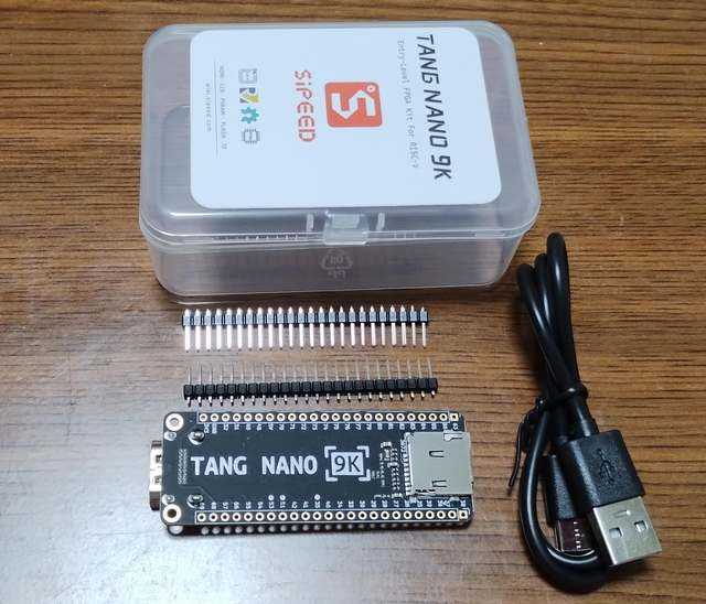
今日は早めで帰宅は18時半。昨日届いた Sipeed Tang Nano 9K のパッケージは思ったより小さく、中には基板、ピンヘッダ、USBケーブルが入っていました。Tang Nano 9K のパッケージ中身ひと通りのモノが揃ってて、すぐに使えるようになってるのはありがたいところです。っちゅうことで、折角なので、ピンヘッダを基板に取り付けました。ピンヘッダを取り付けたこれでブレッドボードなどに固定して使うことができます。開発ツールはGOWIN EDA ホームからダウンロードできるようですが、今から始めると沼る可能性があるので、やめときます。(^^;--- 19:45 ---
August 1, 2023
コメント(0)
-
Tang Nano 9K は明日にも到着しそうだ
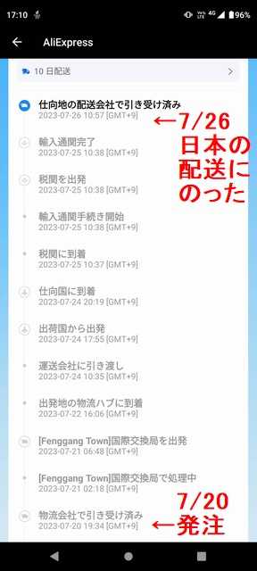
今日は早めで帰宅は18時過ぎ。7/20(木)に Aliexpress でTang Nano 9K を注文したのですが、その際、10日配送のマークのある業者に注文しました。さて、どれぐらいで配送されるか??と配送状況を見てたのですが、今日7/26(水)に日本の配送業者に渡ったことが分かりました。1週間で日本までやってきた中国国内で4日しかかかっていませんね。通常の Aliexpress やと、中国国内でもたもたしててナカナカ国境を越えないことが多いのですが、10日配送、を謡ってる場合には早く処理できているようです。やればできるやん、っちゅうとこですね。今日の時点で国内配送業者に渡ってるので、明日には到着しそうです。10日配送の表示が付いてる商品を合計で日本円700円ちょいぐらい(5米ドル)以上買うと10日配送が適用されるようです。5米ドル以上の商品売ってるのに表示のない店もあるので、店によって違うんでしょうね。っちゅうことで、Aliexpress の 10日配送 はどうやらちゃんと10日以内に配送される、っちゅうことが分かりました。これからは10日配送の店で買うようにしよう。--- 18:45 ---
July 26, 2023
コメント(0)
-
Tang Nano 9K を注文した
今日は早めで帰宅は18時過ぎ。何かおもしろいものはないか、とネットをさまよっていると、GOWIN社のFPGA GW1NR-9 を搭載した開発ボードが Tang Nano 9K として Sipeed から出てるようだ、っちゅうのを見つけました。最近、作りモノからは遠ざかっていたので気づいていませんでしたが、去年の夏ごろには秋月電子でも扱っていたようです。今でも秋月電子で2.48千円で売られています。Sigezoneでも扱っているようですが、現在は在庫切れのようです。っちゅうことで、秋月電子で買うと見せかけて、Aliexpressで注文してみました。(^^; 千個単位で販売実績のあるセラーで2千円+385円送料で売られてたのですが、最近出てきた10日配送、っちゅうのに対応しているようです。秋月電子より断然安いわけではないのですが、10日配送でどれぐらい早く届くか確認する意味もあります。今日(7/20)注文して8/2到着予定となっています。営業日で数えると10日ほどなので、この頃にはやってきてくれることを期待します。で、Tang Nano 9K で何やろうか?? (^^;;--- 18:50 ---
July 20, 2023
コメント(0)
-

OpenSea に出品してみた
今日は晴れ。でもひんやりとしている。大学同期のネット飲み会で、NFT(Non-Fungible Token)を利用するアート作品の出品をやってみろ、と言われ、興味があったのでやってみました。NFTについての詳細はググってみるといっぱい出てくるので割愛。(^^;NFTで作品を出品するにはどうしたらよいのか分からないのでググります。とりあえず、【5分でわかる】NFTの始め方は?アートを売買する方法&高く売るコツについて解説!を参考にやり始めました。売買に共通してる手順はどうも下記のようです。(1) 仮想通貨取引所に登録する(2) イーサリアムを購入する(3) ウォレット(MetaMask等)を作成する(4) ウォレットに入金する(5) マーケットプレイス(OpenSea等)に登録する(1) は既にbitFlyerに登録しているので問題なし。(2) は前にビットコインで損切りした(^^)ときの残金があったのでイーサリアムを1万5千円分ぐらい購入。何かOpenSeaでの初回出品料として1万円ぐらい取られるらしいので... (^^;;(3) はMetaMaskというウォレットがお勧めのようです。Firefox のアドオンMetaMaskかChromeの拡張機能MetaMaskをインストールするとMetaMaskの初期画面がでてきます。MetaMaskの初期画面この先に進むとウォレットをインポートするか作成するか聞いてくるので、初めての場合は作成します。作成方法はMetaMask(メタマスク)とは?スマホ・PCでの使い方を解説などを参考にしてください。ここで注意しなければいけないのはSecret Recovery Phrase は絶対メモ(電子的でも紙でもいいけど)しておき、絶対無くなさないようにすること、公開しないようにすることです。MetaMask自体は色んなブラウザやスマホアプリでも使えますが、ウォレットをインポートするときにこのフレーズが必ず必要になります。また、これを他人に知られるとウォレットを乗っ取られることになるので、絶対に公開してはいけません。(4) MetaMaskの設定が終わるとアカウントに紐づけられたアドレスが生成されているので、そのアドレス宛に仮想通貨取引所からイーサリアムを出金します。他のウォレットに出金する場合、仮想通貨取引所では手数料が取られるので、購入したイーサリアム全額を出金することはできません。手数料分少なくなります。(5) NFTのマーケットプレイスとしてはOpenSeaが大きいようなので、OpenSeaを利用することにします。OpenSeaのページを開き、右上の方に並んでるアイコンの中で人型みたいなを選びます。このアイコンを選ぶすると、どのウォレットと接続するか?という画面が出てきます。ウォレット選択画面ここで先ほどイーサリアムを送金したMetaMaskを選ぶとMetaMask側で署名を要求するウィンドウが開くので署名をします。すると、OpenSeaとウォレットが紐づけられます。この後、ユーザIDとか登録したような気がするけど、少し前だったので忘れてしまいました... (^^;;この後、OpenSeaに作品を登録して販売するわけですが、私は【初心者向け】世界一分かりやすいNFT出品解説 -OpenSea(オープンシー)編を参考に行いました。大体、こんな感じです。(1) コレクションを作成する(2) 作品をコレクションに紐づけて登録する(3) 作品を販売するどのステップも上記ページを参考にすれば、そんなに問題なく実行できると思います。私が少しハマったのが、(2)で作品をコレクションに紐づけるのを忘れたときです。このときでも作品のページから「編集」ボタンを押せばその作品に関する情報を編集することができます。編集で修正できるそんなこんなでOpenSeaで作品を出品することができました。OpenSeaのページ(pa8art) アカウントでPa@ARTを取りたかったけど、既に取られていたので、pa8artになりました。(^^;; こんな感じ初回の出品料が1万円ぐらいかかる、と聞いてたのですが、ウォレットの残高に変化がない... 出品のときのガス代もどうなってるんやろ?? と多少気にはなりますが。(^^;;まぁ、ネット飲み会から始まった話なので、売れるかどうかはどっちでもいいのですが... 売れるに越したことはない。(^^;;--- 13:50 ---
November 6, 2022
コメント(0)
-

GarageBandで遊びたかったので iPad mini4 のジャンクを買った(^^;
今日は晴れて暑い。GarageBandで前から遊んでみたかったのですが、私の持っている iOS デバイスは、iPhone 6、iPhone 6Plus, iPhone 5s、と iOS 12 止まりの機種ばかりでした。GarageBand は iOS 15以降でないと動作しないので、遊ぶことができてませんでした。そんなとき、某オークションでジャンクな iPad mini4 (WiFiモデル 128GB)が出品されていました。iPad mini4 は iOS 15 対応してるし、タブレットやし、っちゅうことで、気が付いたら落札していました。そんなに高くはなかったけど... (^^; ジャンク理由もフレームに割れがある、とか、ホームボタンが陥没してる、とか軽微なモノやったので助かりました。ただ、バッテリがへたってるので、アプリを使ってるとみるみるバッテリ残量が減っていきます。(^^;;さて、GarageBand ですが、最初は使い方がさっぱり分からんかったので、色々サイトを見てたら、8小節だけならそれっぽい音を出せるようになりました。ビートシーケンサの使い方もイマイチ分かってないせいもあると思うのですが... 私はキーボードを弾いたりはできないのですが、ループの中の音源を適当に使うことによってそれっぽくすることができています。(^^;;テストで作った音まだまだ分からないことが多いですが、それっぽい曲を作れるようになるとよいなー、と思っています。(^^;;--- 14:50 ---
May 29, 2022
コメント(0)
-
神田装備で確保した Spartan 3E Starter kit を動かしてみた
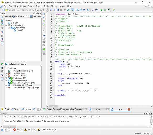
今日は早めで帰宅は18時過ぎ。神田装備で確保して放置していた(^^) Xilinx の FPGA 評価ボード Spartan 3E Starter kit を動かしてみました。まずは開発ツールをセットアップしないといけないので、ISE Webpack 14.7 をダウンロードします。ダウンロードには Xilinx への登録が必要でした。法人が登録することしか考えてない登録フォームで結構悩みましたが... (^^; ISE Webpack 14.7 Windows 10 と書かれたのがあるので、最初これをダウンロードしてインストールしたのですが、Virtual Box の最新版をインストールしないとエラーが出るし、起動しても仮想マシンベースで非常に使いにくかったので 14.7 無印をダウンロードしました。ISE Webpack 14.7 はそのままでは Windows 10 でうまく動かないようです。インストール後にWindows8以降のOSでISE WebPACKを動かすを参考に修正を行ってください。ISE Webpack のライセンスは Help の Manage License からウィンドウを開いて Acquire a License タブで Get My Purchased License を選んで進んでいくと Xilinx のサイトにログインして無料ライセンスを取得することができたはず(手順をメモるのを忘れた(^^;;)。取得したライセンスファイルを Locate Exisiting License で指定すればいけたはず。うろ覚えでスイマセン。(^^;;ISE Design Suite 14.7 を起動して、New Project でプロジェクトを作ります。Wizardに従ってプロジェクト(トップモジュール?)を作ります。ひな形のソースファイルができるので、それに加筆していきます。今回は内部クロックの50MHzを26ビットカウンタでカウントして、その上位8ビットを Spartan 3E Starter kit の 8つのLEDに出力する Verilog HDL ソースを書きました。読めるかな(^^)ソースだけだと論理合成(Synthesize - XST)はできますが、配置配線(Implement Design)ができません。配置配線するには一度論理合成してから ucf ファイルを作成します。ウィザードもあるのですが、使い方が分からなかったので、spartan3e.ucfを参考にクロック(CLK_50M)やLEDのピンを割り振っていきます。こっちも読めるかなこれで配置配線もできます。配置配線が終わったら FPGA に書き込むためのbitファイルを作成(Generate Programming File)します。その後、Spartan 3E Starter kit をUSBケーブルでPCと接続し、iMPACTを起動(Configure Target Device)します。Boundary ScanでInitialize ChainするUSBケーブル経由でJTAGチェーンが見えるようで、Boundary Scan で Initialize Chainするとデバイスが表示されます。xc3a500e が FPGA なので、この上で右クリックして Assign New Configuration Fileを選んで、先ほど作成したbitファイルを選択します。その後、もう一度右クリックして Program を押すと FPGA に bitファイルが書き込まれ、回路が動作し始めます。動作してる様子ボード上のピン曲がりも結構あるので動作するかどうか怪しかった Spartan 3E Starter kit ですが、元気に動いてくれました。ボード上には LCD や VGA コネクタ、ロータリエンコーダにスイッチ類が付いてるので色々遊べそうです。Verilog HDL はすっかり忘れてしまってますが、これを機会に復習してみるか... (^^;;--- 19:40 ---
December 1, 2021
コメント(0)
-
USBオシロスコープ ISDS205A を入手した
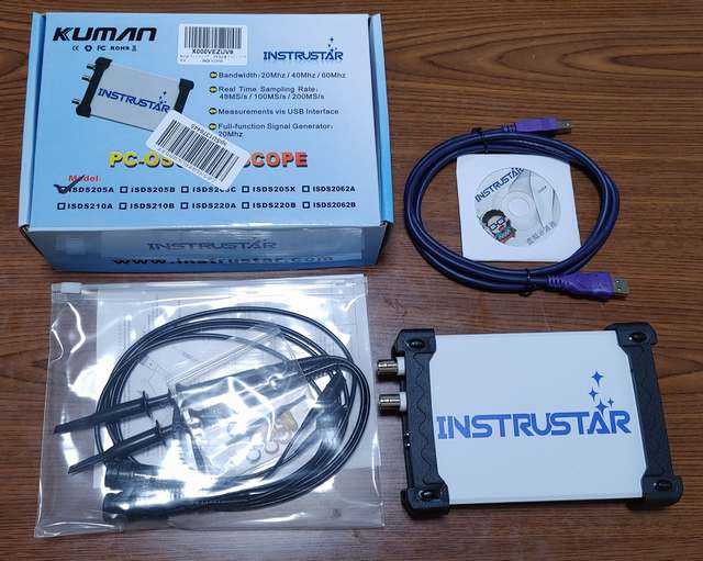
今日は早めで帰宅は18時過ぎ。mouse computer MB-B507H の通電しない原因を探るにはプローブ先の細いテスターが必要です。いや、ここで発想を転換して、プローブの先が細いUSBオシロスコープを確保するのはどうだろうか?! (どういう発想の転換や(^^;)っちゅうことで、某ワンクリックなところで物色したところ、48MS/sec サンプリングで 20MHz 帯域の USBオシロスコープ KUMAN ISDS205A を発見しました。2ch あるし、20MHz まで測れるし、電子工作にも重宝しそうなので、これを確保。(^^;;パッケージ内容USBオシロスコープ本体、プローブが2本、PC接続用USBケーブル、ソフトウェアのCDが入っていました。ソフトウェアは最新のものがよかろうと、メーカサイトを見に行ったのですが、めっちゃ回線速度が遅い(56kbpsモデムより遅いかも(^^;;)ので、最新ではないけども新しめのソフトウェアが置いてあるGitHubのメーカサイトからMulti VirAnalyzer V3.12.1.1をダウンロードしました。これを VB-R 二号機(Core i5 6200U 2.2GHz, メモリ4GB, Windows 11 Insider Preview)にインストール。Windows 11対応なんてどこにも書いてませんが問題なく動作しました。Rspberry Pi Pico の NTSC 信号出力を観測接続は簡単でUSBオシロスコープをUSBケーブルでPCに接続し、プローブで測定点をクリップするだけ。PC側ではオシロスコープソフトウェアを立ち上げます。ソフトウェアで測定開始する方法が最初分からなかったのですが、CH1やCH2と書かれてるところをクリックして横のLED風表示が緑色になれば測定開始です。PC画面上で測定できているNTSC信号の確認をせずに Raspberry Pi Pico のデバッグを行っていたのですが、このようにオシロスコープ画面で確認していれば、もっと効率的にデバッグできたかも。(^^;; 一応サンプリングオシロスコープなので、波形のワンショット記録なんかもできます。カーソルを出せば、時刻差や電圧差が測れるので、信号周期なんかも計算してくれます。垂直同期信号周期は64usecになっているナカナカ便利なツールが手に入りました。当面は高級テスタとして、MB-B507Hの各部電圧測定に使用される予定ですが... (^^;; 解析がはかどるといいけど。--- 19:10 ---
October 7, 2021
コメント(0)
-
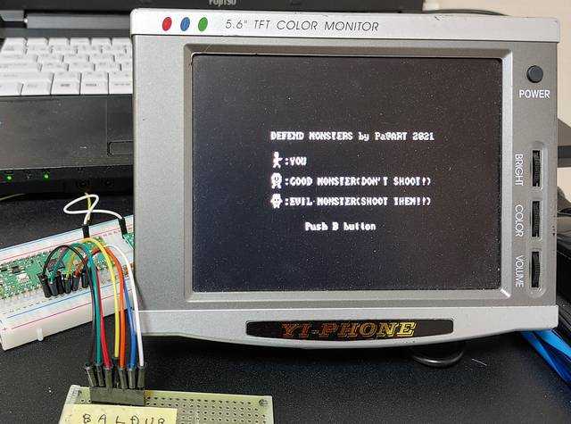
Raspberry Pi Pico 用のゲームを作ったのだが...
今日は在宅勤務。お外は少し冷えていました。コートでも可、っちゅう感じ。---細々と作り続けていた Raspberry Pi Pico 用ゲーム第3弾(?) "DEFEND MONSTERS" が一応完成しました。タイトル画面プレイ画面丸っこいモンスターをとげとげのモンスターから守る、っちゅうゲームです。とげとげのモンスターを全部(規定数)ショットガンで倒すとステージクリア。丸っこいモンスターが全部とげとげのモンスターに食われるとゲームオーバーです。もちろん、自分の体力(HP)が無くなってもゲームオーバーです。自分もモンスターも障害物のあるところは通れないし、ショットガンの弾も障害物で遮られます。作ってはみたもののゲームバランスがイマイチ取れてなくてプレイが単調になってしまいます。動くものが4種類(自分、モンスター2種類、弾)と動かないものが1種類(障害物=サボテン(^^)あって、それなりにコーディング量もあるのですが、動きがイマイチかも。当たり判定が厳しめなので、そこも問題かもしれません。っちゅうことで、改良は連休中の宿題かな。ソースの公開は改良が済んでからにします。一応プレイ動画--- 19:20 ---
April 26, 2021
コメント(0)
-
OneDrive上のRaspberry Pi Picoソースビルドでエラー
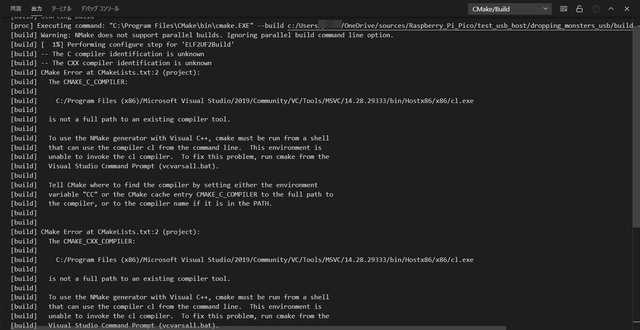
今日は曇り。曇ってても気温は高めです。---Raspberry Pi Pico のソースファイルはOneDrive上に置いて単身赴任先でも自宅でも開発ができるようにしています。神田装備で確保した dynabook AZ35/GB(Core i5 8250U, メモリ16GB, SSD512GB)で新たにRaspberry Pi Picoの開発環境を整えたところ、ソースのビルドでエラーが出ました。ビルドエラーが出るエラーの内容は、[build] -- The C compiler identification is unknown[build] -- The CXX compiler identification is unknown[build] CMake Error at CMakeLists.txt:2 (project):で、C/C++コンパイラが見つからん、といった内容です。また、[build] The CMAKE_C_COMPILER:[build] [build] C:/Program Files (x86)/Microsoft Visual Studio/2019/Community/VC/Tools/MSVC/14.28.29333/bin/Hostx86/x86/cl.exe[build] [build] is not a full path to an existing compiler tool.[build] The CMAKE_CXX_COMPILER:[build] [build] C:/Program Files (x86)/Microsoft Visual Studio/2019/Community/VC/Tools/MSVC/14.28.29333/bin/Hostx86/x86/cl.exe[build] [build] is not a full path to an existing compiler tool.とも文句を言われています。確かに dynabook A35/GB にインストールした Visual Studio 2019の cl.exe のパスは上記と異なっています。これはエラーが出ても仕方がない。(^^;このCMAKE_C_COMPILERとCMAKE_CXX_COMPILERで指定されるパスさえ正しくしてやればエラーは出なさそうなので、Visual Studio Code の拡張機能である CMake Tools の設定で環境変数を定義してみたりしたのですが、同じエラーが出ます。ビルドしたソースは別のPCからビルドした後やったので、どうもそのPCにインストールした Visual Studio 2019 の cl.exe のパスがどっかに残ってるようです。が、どこに残ってるのか探すのは大変... (^^;;それなら、っちゅうことで、buildフォルダを丸ごと消して、フォルダコンフィグレーションをやり直し、ビルドしてみたところ、コンパイルが通りました!コンパイルするPCのVisual Studio 2019のアップデート具合が微妙に違う(cl.exeのパスが違う)ときに、OneDrive上の同じソースをコンパイルしようとすると、この現象に出くわすようです。解決策は、buildフォルダを一度消してビルドするということのようです。もっとスマートな解決法もあるのかもしれませんが... (^^;;--- 11:10 ---
April 25, 2021
コメント(0)
-
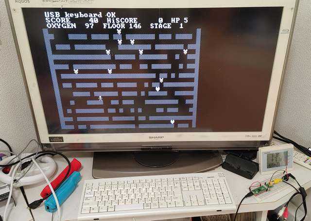
Raspberry Pi Pico 用のゲーム "DROPPING MONSTERS" を USBキーボード対応にした
今日は雨時々曇り。午前中は曇りやったので、散髪に行きました。今日は珍しくおばちゃんに刈ってもらいました。頭スッキリ。---Raspberry Pi Pico の USB ホストモードで USB キーボードを接続したので、USBキーボードからのキー入力を扱うにはどうしたらいいのか、何となく雰囲気はつかめました。っちゅうことで、前に作ったスペースマウスもどきの"DROPPING MONSTERS"をUSBキーボードで操作できるように改造してみました。ソースは、pa-art/test_usb_hostの中にあるdropping_monsters_usbの中にあります。キーを読み取るには、キーボードの状態を格納するhid_keyboard_report_t型の変数を定義して、その変数に格納されたキーコードを変換テーブルを使って対応するキーに変換すればよいようです。キーボードの状態を読み取るにはtuh_hid_keyboard_get_report()関数を使います。引数にポインタ渡ししてるhid_keyboard_report_t型の変数にキーコードとかシフトキーなどの状態が入ってるので、return_key_code()関数でキーの情報に変換します。元々サンプルに入ってた変換テーブルはUSキー配列やったので、日本語配列に近くなるように変更を加えてあります(pseudo_jp106.h)。ただ、この動作を行うためには、Tiny USBのホストタスクであるtuh_task()を無限ループ内で実行している必要があります。また、最初にボードの初期化board_init()とUSBの初期化tusb_init()を呼ばないといけません。あと、コールバック関数、void tuh_hid_keyboard_mounted_cb(uint8_t dev_addr) void tuh_hid_keyboard_unmounted_cb(uint8_t dev_addr)void tuh_hid_keyboard_isr(uint8_t dev_addr, xfer_result_t event)を定義しておかないとコンパイルが通りません。(^^;と、色々ややこしいのですが、何とかUSBキーボード対応に改造することができました。USBキーボード対応の"DROPPING MONSTERS"ただ、家のUSBキーボードは認識されるときとされないときがあって、その識別のために画面の一番上に表示を追加しています。TinyUSBが何をしてるのか分らんのですが、NTSC表示にノイズが乗ることから割込も使ってるのかな??USBキーボードでプレイしているところRaspberry Pi Pico + TinyUSB でのUSBキーボードの使い方は何となくわかったような気がします。--- 15:15 ---
April 17, 2021
コメント(0)
-

ASCIIアートのGirlとLenna (^^;
今日は在宅勤務。画像をASCIIアートに変換してくれるページ、AA変換(アスキーアート生成)、があったので、SIDBAの標準画像の Girl と Lenna をASCIIアートに変換してみました。SIDBAの標準画像は、神奈川工科大学 情報学部 情報工学科 信号処理応用研究室のダウンロードページからもらってきました。で、何をしたかというと、Raspberry Pi Pico の NTSC出力で表示させてみた、というそれだけです。(^^;Girl の原画像をPNGにしたものGirlのASCIIアート(ネガ状態)GirlのASCIIアート(ポジ状態)ポジ状態は画像変換ソフトでネガポジ反転したモノです。ポジ状態にすると何となく雰囲気は出てるような気がします。(^^;; 同様に、Lennaは...Lennaの原画像をPNGにしたものLennaのASCIIアート(ネガ状態)LennaのASCIIアート(ポジ状態)こちらもポジ状態だとそれっぽくはなります。いずれにせよ、小さく表示してるからそれっぽく見えるだけで、クリックして元のサイズで見ると、何だかなぁ、っちゅう感じです。(^^;;まぁ、こんな遊びではなく、ちゃんとグラフィック表示しろ、っちゅうことですか。(^^;; 今のままでは色数が足りん...--- 19:20 ---
April 12, 2021
コメント(0)
-

Raspberry Pi Pico の USB ホストモードで USB キーボードを接続した
今日は晴れ。単身赴任先はまだ少し冷えています。コートを着てもまだ大丈夫。---Raspberry Pi Pico の USB のホストモードを使って、USBキーボードを接続して文字入力するサンプルがpico-examples¥usb¥host¥host_hidにあるので、それを動かしてみることを目標に実験してみます。ホストモードのときの難点は、Raspberry Pi Pico の USB 端子がUSBデバイス用になってしまうため、5V電源を Raspberry Pi Pico に接続しないといけないことです。ブレッドボード上で 5V 電源を Raspberry Pi Pico に供給するために、秋月電子通商で売ってる、ブレッドボード用DCジャックDIP化キットを使って、5V ACアダプタから電力供給してみました。このとき、+5V → VBUS (40ピン)とします。GNDはRaspberry Pi PicoのどのGND端子につないでも構いません。Raspberry Pi Pico と USBキーボードはどうやって接続するかっちゅうと、Raspberry Pi Pico のマイクロUSB端子に OTG ケーブルを挿して、その先にUSBキーボードを挿します。さて、サンプルのhost_hidはメッセージとか入力されたキーを標準出力に出力しています。最初、USBシリアル変換を Raspberry Pi Pico につないで TeraTermでそれらの出力を見ようとしてたのですが、文字化けしたりしてどうもうまくいきません。仕方ないので、標準出力に出力している内容をNTSCモニタに出力するようソースを少しいじりました。これで、USBキーボードで打った文字がNTSCモニタに表示できるようになりました。ソースはpa-art/test_usb_hostにあります。メインは host_hid.c です。Raspberry Pi Pico と USBキーボード接続の様子host_hid.cで何をやってるかイマイチ理解できてないので、USBキーボード入力部分を切り出して自分のプロジェクトに組み込みところまではまだまだですが、とりあえず、Raspberry Pi Pico のホストモードで USBキーボードが使えることは分かりました。USBキーボードから入力している様子(ちょっと見にくいけど(^^)--- 16:15 ---
April 10, 2021
コメント(0)
-
Raspberry Pi Pico の NTSC 信号生成を別ファイル化した
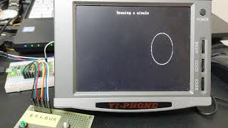
今日は早めで帰宅は18時過ぎ。Raspberry Pi Pico の NTSC 信号生成もだいぶこなれてきたので、そろそろ関数群を別ファイルにまとめて使いやすくしました。pa-art/pico_ntscにファイルを置きました。releaseオプション(速度最適化)でコンパイルする必要があります。pico_ntsc_grph.cに関数群が入っています。// initialize video and LED GPIOinit_video_and_led_GPIO();// initialize and start PWM interrupt by 64us periodenable_PWM_interrupt( );これでグラフィックVRAMにデータを書けば画面に表示されます。ドットの描画は、// to write a value into graphical VRAM located at (x, y)void gvram_write ( int x, int y, unsigned char value );です。valueは色で黒=0、白=1、グレー=2です。文字を描画するときは、// put a character on VRAMvoid gvram_put_char( int x, int y, char c, char col );// put strings on VRAMvoid gvram_strings( int x, int y, char *mes, char col );を使います。colは色で先ほどと同じです。このように関数をファイル分けしてからなぜか処理速度が上がり、画面の解像度が上がりました。(^^; 400x200ぐらい表示できるようです。ただし、縦横比が違うので円を描いても縦長になります。pa-art/pico_ntscには今のところ、・dropping_monsters:スペースマウスをリスペクトした(^^)ゲーム・graphic_demoがサンプルとして入ってます。graphic_demoを実行した様子(円が縦長(^^)これで色々作れそうになってきました。ただ、USBキーボードを接続して使いたいので、そっちの実験を優先するかもしれません。(^^;;--- 20:40 ---
March 25, 2021
コメント(0)
-
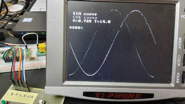
Raspberry Pi Pico の NTSC 出力のVRAM構成をドット毎にしてみた
今日は早めで帰宅は18時過ぎ。Raspberry Pi Pico の NTSC 出力を行う際に今まではキャラクタVRAM方式を使ってました。VRAMにはキャラクタコードが格納されていて、水平同期信号に合わせて、そのキャラクタを描画する、という方式です。この方式はVRAMサイズが小さくて済む、という利点があります。しかし、Raspberry Pi Pico には 264kB ものメモリがあるので、256x192のグラフィック画面に対して、1ドットをunsigned char (1バイト)で表しても48kBぐらいの VRAM サイズで納まります。残り200kBもあるなら VRAM にこれぐらい使ってもよかろう、っちゅうことで、unsigned char gvram[256][192];のように VRAM を確保して、水平同期信号に合わせて、1ドットずつ描画することにしました(グラフィカルVRAMと呼ぶことにします。)。この方式を使えば、現状の回路で1ドットに対して白、グレー、黒を表現することができます。もっと頑張って外付け回路作れば1バイト=8ビット→256階調を表現することができるようになると思いますが、とりあえずは頑張らない。(^^;1ドット毎の描画っちゅうことなので、文字表示するためには文字を1ドットずつグラフィカルVRAMに書き込む関数を作る必要がありますが、フォントファイルがあるのでそんなに面倒でもありませんでした。っちゅうことで、pa-art/test_ntscのtest_ntsc_grph.cとしてグラフィカルVRAMのテストプログラムを置きました。sinカーブもちゃんと描ける黒描画のタイミングが白/グレーに対して少し違うようなので、右端に行くほどフォントが潰れやすくなっているような気がします。何とかならんかな。(^^;;また、ドットとしてグレーが表現できるようになったので、"DROPPING MONSTERS"の壁部分をグレーにしてみたバージョンをpa-art/test_ntscのtest_ntsc_wall_grph.cとして置きました。とりあえず動かすことを目標にしたのでソースとは汚いですが... (^^;;壁がグレーになっている(ハッシュパターンも込みで)見た目は前とあまり変わりませんが、内部的にはキャラクタベースのマップ(vram)に描画用のVRAM(gvram)を追加して論理はほとんどいじらずに描画を変更しています。なので、見にくい。(^^;; 最初から設計しなおしたら違う実装があると思います。グラフィカルRAM版の"DROPPING MONSTERS"プレイ動画グラフィカルRAM版のNTSC出力の方が融通が利きそうなので、これからはこちらをベースにしていきたいと考えています。ドットの微妙なズレを何とかしたいけど...--- 21:20 ---
March 22, 2021
コメント(0)
-

春分の日だ
今日は曇り時々晴れでそれなりの気温。今日は春分の日、昼と夜がほぼ同じ時間の日です。東京やとだいぶ春になった気がします。単身赴任先やともうちょっと経たんとあかんのやろな。---家のテレビに Raspberry Pi Pico の NTSC出力をつないだところ、上下が少し切れるけれども安定して表示されることが分かりました。"DROPPING MONSTERS"プレイ中単身赴任先で開発用に使ってる小さいモニタでは文字が滲んで見にくいのですが、まともなモニタやとドットがくっきり映るんですね。(^^;昼食を食べてからは、"DROPPING MONSTERS"のゲームパラメータの調整をしたり、"FLYING METEOR"にシューティング要素を加えたりしてました。ソースファイルはいつものpa-art/test_ntscにあります。平和な春分の日です。--- 15:15 ---
March 20, 2021
コメント(0)
-
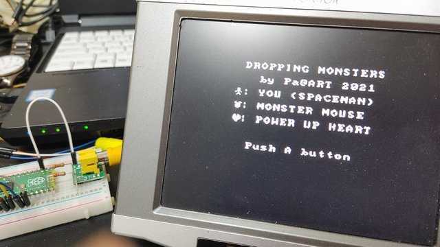
Raspberry Pi Pico のゲーム第2弾 "DROPPING MONSTER" (芸夢狂人さんへのオマージュ)
今日は早めで帰宅は18時過ぎ。その昔、PC-8001のゲームで遊んでいた頃、芸夢狂人という方が I/O 誌にゲームをたくさん投稿されてました。その中でもスペースマウス、っちゅうゲームが面白かったので、もう一度遊びたいのですが、いかんせん、PC-8001は動くかどうか分からん状態。(^^; それなら自分で作ればいいのでは?? と考えてました。っちゅうことで、以前、Ichigo Jam の BASIC で作ろうとしたのですが、謎のバグに悩まされ断念した経緯があります。今回、Raspberry Pi Pico で NTSC ビデオ信号を出せるようになり、簡易ゲームパッドも作ったことやし、Raspberry Pi Pico 上で作ってみたら割とあっさり似たようなゲームが作れました。スペースマウスっちゅうゲームは、・迷路状になった階をスペースマウスを避けながら上へ上へと昇っていく・下へは移動することができない・ハート形のパワーアップアイテムを取ると一定時間壁をぶち破って上へ進むことができる・スペースマウスやハートは一度左右のいずれかに動き出したら向きを変えることはない・スペースマウスやハートは穴があると必ず下へ降りてくる・250階まで行ったらその面はクリア・酸素(Oxygen)ゲージがあって、それがゼロになるとゲームオーバーという私の記憶を元に作成したのが "DROPPING MONSTERS"です。(^^;; ソースは、pa-art/test_ntscのtest_ntsc_wall.cです。コンパイル時にはReleaseオプションでコンパイルする必要があります。オープニング画面ゲーム開始直後開始直後は地面の上にいる設定なので、下は全部*で埋めてます。もうすぐクリアクリア(今回は150階の設定)直前になると屋上が見えてきます。ステージクリアステージクリア時に残り酸素に応じてボーナスがもらえます(オリジナルと同じ)。ステージボーナスも追加しました。(^^; また、3,000点毎にライフが1増えます(オリジナルは5,000点やったかな)。ゲームオーバー上階に行くほどモンスター(スペースマウス)の出現数と移動速度が上がるようにしてあるので、終盤立ち止まってしまうと、モンスターの隙を伺うのが大変になってます。(^^;; 移動アルゴリズムは分かってるのですが...プレイ動画自分で作ったのにナカナカ面クリアできないので、くやしいです。(^^;; オリジナルと同じ250階設定にしたらたぶんクリアできない... しかし、8ビットマシンでスペースマウスを作り上げた芸夢狂人さんは素晴らしい人です。尊敬してます。--- 20:05 ---
March 17, 2021
コメント(0)
-
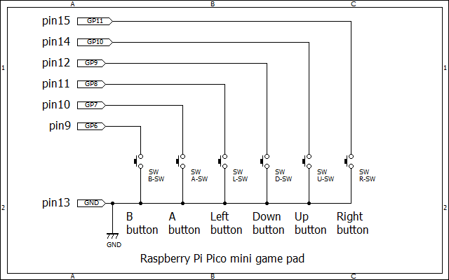
Raspberry Pi Pico用ミニゲームパッドと簡単なゲームを作った
今日は晴れ。Raspberry Pi Pico で NTSC ビデオ信号を出せるようになったらやってみたいのが、ゲーム作成。(^^; しかし、Raspberry Pi Picoにはまだ汎用キーボード(PS/2とかUSBとか)をつなげられるようにしてないので、タクトスイッチを使って簡易的なゲームパッドを作成しました。結線図上記の結線図のように配線します。プルアップ抵抗はRaspberry Pi Pico 内蔵のプルアップ抵抗を使用すればよかろう、と省略してあります。(^^;; Left/Right、Up/Down は十字に配置、A/Bはその左側に適当に配置しました。赤がA、緑がBこれを使って遊べる簡単なゲームを作ろう、っちゅうことで作ったのが "FLYING METEOR!!" です。(^^;; "FLYING METEOR!!"のタイトル画面"FLYING METEOR!!"のゲームオーバー画面よくある横方向に流れてくる障害物を避ける系のゲームです。メテオを避けて、ハートマークを取る(ボーナス点が加算される)というだけのゲームです。一応、スコアが上がるとメテオのスピードと出現頻度は変わるようになってます。実は手抜きでメテオとハートマークの動きルーチンは同一です。(^^;; ソースファイルは、pa-art/test_ntscのtest_ntsc_shot.cです。ファイル名にshotが入ってるのはシューティングにしようとしてた当初目論見の残骸です。(^^;;メテオの綴りは meteor です(^^;;上記のプレイ動画では撮影しながらゲームをしたので、動きがカクカクです。また、タイトルの Meteor が Meteo になってます。(^^;; これに気づいたのは動画をアップロードした後なので、まぁ、いいか、とこのままにしています。--- 11:35 ---
March 14, 2021
コメント(0)
-

Raspberry Pi Pico のライフゲームをデバッグした(^^;
今日は早めで帰宅は18時過ぎ。Raspberry Pi PicoのNTSC出力でライフゲームを実装したけども、アルゴリズムにバグがあるのを発見。ライフをアップデートするとき、元々のライフマップに結果を書いてたけど、それをやるとライフのルールが乱れてしまいます。(^^; アップデートするライフマップを別に作って、それを最後に元のライフマップにコピーする必要がありました。これで普通のライフゲームのように最後はライフマップが定常状態に陥るようになりました。ライフの数がある一定時間変化しないとき、定常状態になったと判定してライフマップをリセットする機能も付けました。修正後のソースファイルは、pa-art/test_ntscのtest_ntsc_lifegame.cになります。デバッグ後のライフゲームの様子これでライフゲームについては一段落かな。--- 19:05 ---
March 12, 2021
コメント(0)
-

Raspberry Pi PicoのNTSC出力でライフゲーム
今日は早めで帰宅は18時過ぎ。Raspberry Pi Pico の NTSC水平同期信号生成を PWM 割込に変更したので表示が安定しました。動作速度を上げれば、水平方向に描画できるドット数が増えるので、コンパイルオプションを Release (速度最適化)にしてコンパイル。すると、なぜか割込がかからなくなったので、割込の優先順位を上げてやると割込がかかるようになりました。?? 割込の優先順位を上げるには、irq_set_priority(PWM_IRQ_WRAP, 0xC0);を追加しました。また、白ドット描画と黒ドット描画に微妙な時間差があるようで、フォントの描画ルーチンに時間調節を入れてあります。これもよく分かりません... (^^;これだけ実施すると横30キャラクタ、縦28キャラクタまで描画できるようになりました。っちゅうことで、デモ用にライフゲームを実装しました。といってもアルゴリズムは、 maze1230/lifegame.c を参考にさせてもらいました(移植した(^^;;)。ソースファイルは、 pa-art/test_ntsc の test_ntsc_lifegame.c です。Raspberry Pi Picoにライフゲームを実装一応、乱数の初期化にはADCの5個の値の和をsrand()の引数に渡してランダム化を図っています。やはり何パターンかにはなるようですが、ある程度のランダム化はできているようです。こうなってくると入力系を作って何かゲームでも作ってみたくなりますね。--- 18:45 ---
March 11, 2021
コメント(0)
-
Raspberry Pi Pico の乱数の種にADC値を使ってみたが...
今日は早めで帰宅は18時過ぎ。Raspberry Pi Pico で乱数(擬似乱数)を発生させるときにrand()を使うのですが、srand( unsigned int seed)に与える種(seed)をランダムにしないと同じ乱数系列が出てしまいます。時刻を取得できるシステムであれば、プログラムを起動したときの時刻を乱数の種に使うことで同じ乱数系列の発生を避けることができます。Raspberry Pi Pico ではRTC機能を持っているものの、システム起動してからの時刻は常に一定となるはずなので、乱数の種には使えません。代わりに使えそうなランダムなものとしてはADCの値があります。ADCの入力に何もつないでないときにはノイズとしてLSB付近がフラフラしてると思われます。また、ADCの4番には温度センサがつながっているので、電源入れた直後は気温に応じたランダムな値を持っていることが期待できます。温度センサが定常状態になるとあまり期待できませんが... (^^;っちゅうことで、乱数の種としてADCの5系統の入力を加算した値を使ってみましたが、完全にランダムにはならず、何系統かの種の値になるようです。温度センサが定常状態になってから試したので、そのせいもあるかもしれませんが...まぁ、それでも何パターンかのバリエーションはできるみたいなので、無いよりはマシかな、っちゅう感じです。--- 20:05 ---
March 9, 2021
コメント(0)
-
Raspberry Pi Pico の NTSC水平同期信号生成を PWM 割込に変更した
今日は早めで帰宅は18時過ぎ。Raspberry Pi Pico で NTSC モニタに出力したときには、水平同期のタイミングは結構いい加減に(自分でタイミングを合わせるように)作ってました。これをタイマを用いた割込ベースのタイミング生成にしようとしてたのですが、タイマ使用中はsleep_us()が使えないので、水平同期信号の時間が制御できませんでした。っちゅうことで、タイマの代わりにPWMのカウンタが設定値になったときにかかる割込(PWM_IRQ_WRAP)を使って、一定間隔で水平同期信号を発生させることにしました。この割込を有効にするには、まず PWM で使用するピンを決めてスライス番号を設定する必要があります。// GPPWM pin is the PWM outputgpio_set_function(GPPWM, GPIO_FUNC_PWM);// Figure out which slice we just connected to the GPPWM pinuint slice_num = pwm_gpio_to_slice_num(GPPWM);この後に、スライス番号に対するPWM割込をクリアしてからPWM割込を有効にします。pwm_clear_irq(slice_num);pwm_set_irq_enabled(slice_num, true);次に、PWM割込(PWM_IRQ_WRAP)に対する割込ハンドラ(水平走査線の処理=垂直同期+水平同期+フォント描画を行う関数、ここではhorizontal_line)を設定してから、PWM割込を有効にします。irq_set_exclusive_handler(PWM_IRQ_WRAP, horizontal_line);irq_set_enabled(PWM_IRQ_WRAP, true);この時点ではまだPWMが有効になってないので割込はかかりません。さて、割込の周期を決めてやる必要があります。Raspberry Pi Pico のクロックは125MHzなので、クロック1発分の長さは 8[ns] です。水平同期信号として 64[us] = 64000[ns] の周期にしたいので、クロックを 64000/8 = 8000 回カウントアップしたところで PWM のカウンタが 0 になる(PWM_IRQ_WRAP割込がかかる)ように wrap 値を設定して PWM を有効にしてやります。// Set counter wrap value to generate PWM interrupt by this valuepwm_set_wrap(slice_num, 7999);// Load the configuration into our PWM slice, and set it running.pwm_set_enabled(slice_num, true);これで64us周期のPWM割込(PWM_IRQ_WRAP)毎に水平走査線の処理を行うことができます。プロジェクトはpa-art/test_ntscに置いてあります。見た目は前と変わらんけど... (^^;前は無限ループの中で水平走査線処理を行っていたのですが、今回は割込で水平走査線処理を行うので、無限ループの中では好きな処理ができます。VRAM操作をすれば画面に反映されます。かなりウェイトをかけないと速すぎて困るぐらいです。(^^;; っちゅうことで、ゲームなんかも作れると思います。行ったり来たりしてるバーの表示もかなりウェイトかけてるちなみにコンパイルはデバッグモードで行ってます。--- 20:00 ---
March 8, 2021
コメント(0)
-
水平同期信号をPWM割込で発生させようとしているが...
今日は早めで帰宅は18時過ぎ。Raspberry Pi Pico の NTSC 信号出力で水平同期信号をタイマで動かそうとしたのですが、タイマで呼び出されたハンドラの中ではsleep_us()は使えないのを思い出し、爆死。(^^;割込でハンドラを呼び出せばよいのでしょう、とPWM割込を使おうとしたのですが、PWM周期の設定でハマってしまいました。64us周期に設定したつもりで動かすと、割込ハンドラが1度呼ばれてだんまりを決め込む、という症状に悩んでいます。割込ハンドラが1度しか呼ばれないので、64us周期に設定できたかどうかも分かりません。PWMの使い方がイマイチ分かってないからやろうなぁ。タイマが1系統しかないっちゅうのも考えものです。orz タイマの代わりにPWMを使え、ということなんでしょうが... うーむ、困った。--- 21:30 ---
March 3, 2021
コメント(0)
-

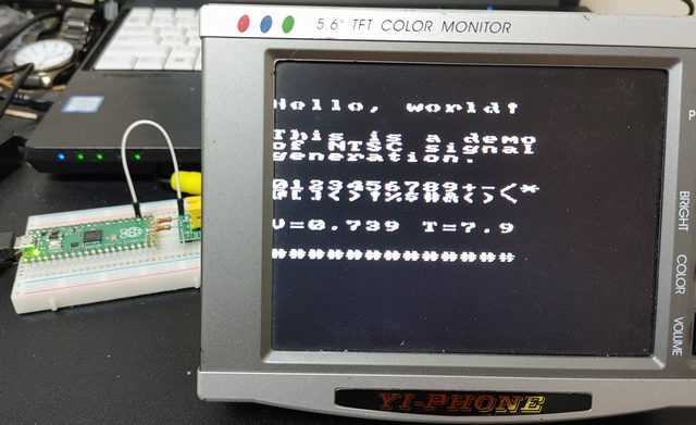
Raspberry Pi Pico で NTSC モニタに出力した
今日は晴れ。Raspberry Pi Pico で NTSC モニタに文字を表示したい、っちゅうことで、色々やってみました。一応、画面に表示されるようにはなったのですが、表示してる途中でフォントが崩れる、とか表示位置が右に寄ってる、とか色んな問題が残っています。(^^;NTSC信号のことをよく知らないのですが、Arduino ビデオ信号/テレビ画面に出力を参考に試してみました。このページを参考に、Raspberry Pi Pico から RCAジャックへの配線は、GPIO14 (19番ピン)~330Ωの抵抗~RCAジャックの真ん中のピンGPIO15 (20番ピン)~1kΩの抵抗~RCAジャックの真ん中のピンGND(23番ピン)~RCAジャックのGNDのピンとしました。これらのピンへの信号出力は遅延があってはいけないようなので、gpio_put_masked()関数を使ってマスクされたピンに'H'/'L'を同時に出力するようにしました。例えば、gpio_put_masked((1<< 14) | (1<<15), (1<<14) | (1<<15));とすれば、GPIO14とGPIO15の両方に同時に'H'を出力することができます。で、何だかんだやってでっち上げたのが、test_ntscというプロジェクトです。ここで使わせてもらったフォントは、 dhepper /font8x8 にあるfont8x8_basic.hで、ASCIIコードの128番目までのフォントが入ってます。VRAMに書かれたデータをNTSCモニタに表示するのが基本動作です。VSYNCの期間にごちゃごちゃすると、動きも付けられるので、デモを入れてあります。このような作り方だと汎用性がなくて使いにくいと思うのですが、とりあえず今の私のレベルではこの辺までです。(^^;; NTSC信号のことをちゃんと勉強しなければ...フォント表示が汚いけどメッセージは表示できた表示中にフォントが崩れるのはナゼ?? orzまだまだ改良、というか根本的に理解して作り直した方がいいかも。(^^;;--- 17:45 ---
February 28, 2021
コメント(0)
-

Raspberry Pi Pico の Timer で Lチカ+α
今日は早めで帰宅は18時過ぎ。Raspberry Pi Pico の C/C++ SDK のドキュメントを読んでて、Timer による繰り返し処理ができそうやったのでやってみました。4.2.12 repeating_timerに出てくる関数を使います。static bool add_repeating_timer_ms (int32_t delay_ms, repeating_timer_callback_t callback, void *user_data, repeating_timer_t *out)で定義されるadd_repeating_timer_ms関数を使います。これだけ見ててもさっぱり分からなかったので、4.1.22. hardware_timerのソースを見たところ何とか使い方が分かりました。delay_msは Timer の呼び出し周期[ms]です。これは分かる。callbackは Timer が呼び出し周期毎に呼び出すコールバック関数です。ただし、関数の型が何だか分からん型なのですが、hardware_timerの例を見ると、bool 型でよいようです。*user_dataはコールバック関数で使うための変数のようですが、よく分かりません。(^^; NULLで呼べばよいようです。*outはrepeating_timer_t型の変数を定義してポインタを渡します。Timer を停止したりするときに使うみたい。ざっくり書くと、bool callback_foo( struct repeating_timer *t ) {コールバック処理}int main() {repeating_timer_t timer; // timer変数の定義add_repeating_timer_ms( 1000, callback_foo, NULL, &timer ); // Timerの起動return 0;}というような書き方をすると、1000[ms]毎に callback_foo が呼ばれてコールバック処理が実行されます。サンプルとして、500[ms] 毎にオンボードの温度センサ値を読み、カウンタを動かし、LEDの状態をトグルして、I2C LCDに温度とカウンタ値を表示するプログラムを作成しました。GitHubのリポジトリにソース一式を置きます。Timer による Lチカ+αTimer を使えば一定時間毎の繰り返し処理が楽になります。--- 20:15 ---
February 16, 2021
コメント(0)
-
Raspberry Pi Pico内蔵温度センサを C で使ってみた
今日は晴れて温い。Raspberry Pi Pico には温度センサが内蔵されてるので、値を取得してターミナルに表示する C プログラムを作ってみました。温度センサは ADC に接続されていて、ADCの4番目の入力の値が温度センサ出力の電圧値になります。この辺りは、Raspberry Pi Pico C/C++ SDKの4.1.1. hardware_adcに書いてあります。センサ出力電圧 V から温度(摂氏) T への変換式は、T = 27 - (V - 0.706) / 0.001721です。また、ADCから読んだ値 D をセンサ出力電圧に変換するには、V = D * CONVCONV = Vref / (1
February 14, 2021
コメント(0)
-
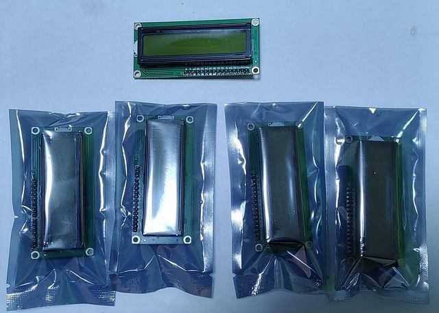
16x2 I2Cキャラクタ液晶モジュールを購入した
今日は早めで帰宅は18時過ぎ。手持ちの 16x2 I2Cキャラクタ液晶モジュールが少なくなってきたので、某ワンクリックなとこで買いました。黄緑バックライトの1602コントローラ搭載な 16x2 パラレルキャラクタ液晶(5V)にI2Cシリアル化モジュールがセットになったモノが5個セットになった商品でした。2千円ちょっとと安かったです。それが今日届いてました。5個セットのI2C液晶モジュールI2Cシリアル化モジュールは別体で液晶モジュールにはんだ付けせんとイカンと思ってたのですが、既にI2Cシリアル化モジュールは液晶モジュールにはんだ付けされていました。これはラッキー。なんせ1個当たり16ピンのはんだ付けがいりますからね。(^^;I2Cシリアル化モジュールは液晶モジュールにはんだ付けされていたさて動作確認のために Raspberry Pi Pico の C プログラムで表示を行ってみました。#よい子は5V液晶モジュールを Raspberry Pi Pico につないじゃダメだよ。(^^;;ちゃんと表示される表示してるのは、Raspberry Pi Pico 上の温度センサの電圧値(v)と温度(T)です。Cプログラムから温度センサを使う方法はまた紹介します。っちゅうことで、I2Cキャラクタ液晶モジュールを安く補充することができました。--- 19:10 ---
February 13, 2021
コメント(0)
-
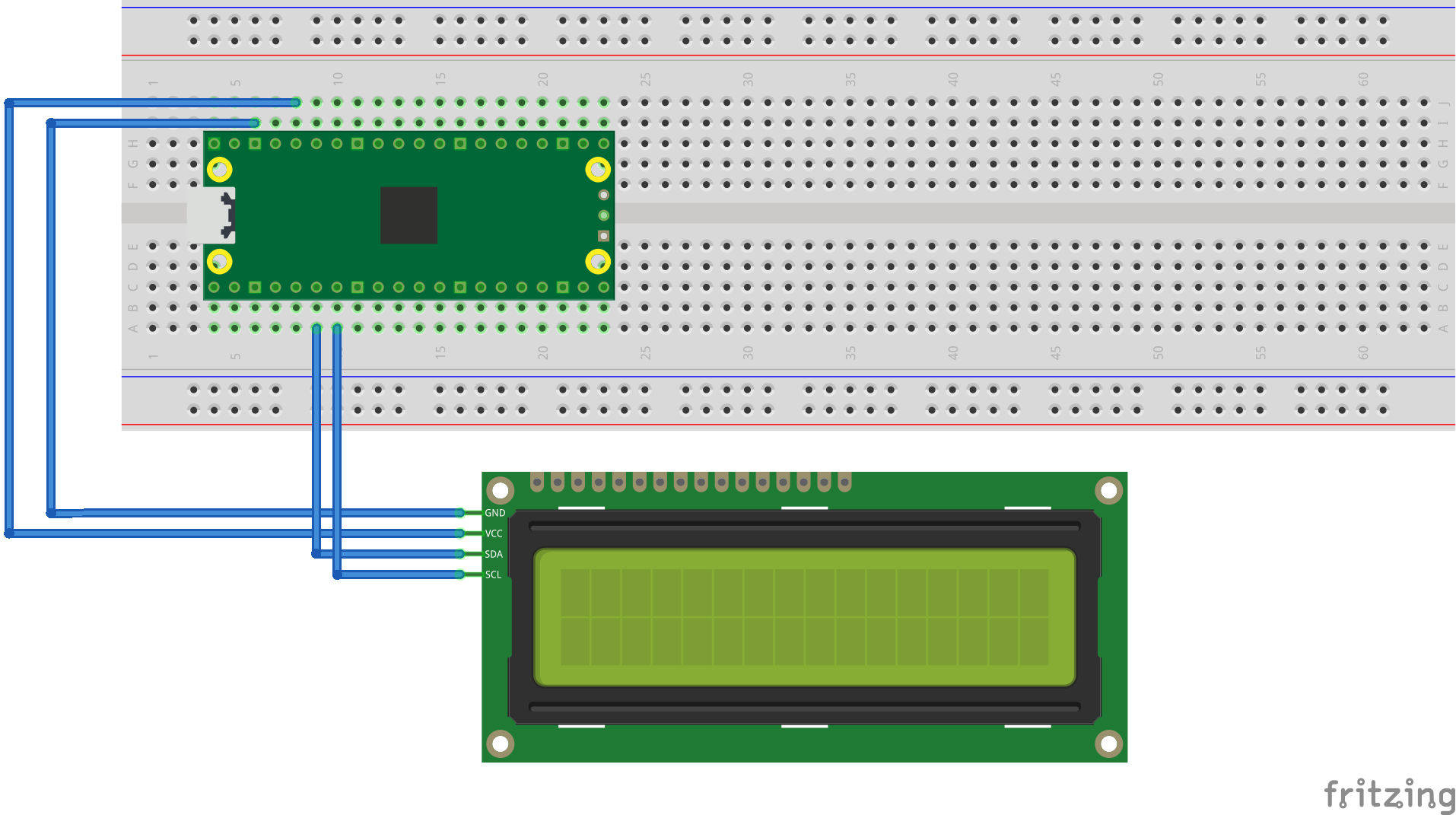
Raspberry Pi Pico に I2C キャラクタ液晶をつないだ
今日は曇りのち晴れ。昨晩降った雪が少し積もってましたが、晴れたのでとけるでしょう。---Raspberry Pi Pico に I2C キャラクタ液晶を接続するサンプルが pico-examples¥i2c¥lcd_1602_i2cにあるので 16x2 I2C キャラクタ液晶を接続してサンプルを動かしてみました。フォルダ内にあるlcd_1602_i2c_bb.png上図のようにキャラクタ液晶を接続します。私は手持ちに5Vなキャラクタ液晶しかなかったので、電源を5V(VBUS)から取りました。RP2040のGPIOは5Vトレラントではないようなのですが、無理やりつないでみました。よい子はマネしない方がいいでしょう。(^^;サンプルをビルドして表示してみたこのソースを流用して何か作ろうと自分でプロジェクトを作成してコンパイルしようとしたのですが、結構手間取りました。(^^;;ソースの編集には Visual Studio Code を使っているので、Visual Studio Code 上で Raspberry Pi Pico プロジェクトのビルドができるように設定します。Getting started with Raspberry Pi Picoの8.2.4. Building "Hello World" from Visual Studio Codeに書いてあるように設定します。ただし、Visual Studio code のDeveloper Command Promptから code と打って起動しないとうまく動かないかもしれません。拡張機能のCMake Toolsをインストールします。その後、Visual Studio code の設定から拡張機能をクリックしてCMake Tools Configurationを選びます。Cmake: Configure Environmentの「項目」のところにPICO_SDK_PATHを、「値」のところにpico-sdkの絶対パスを入力します。ドキュメントには相対パスで書いてありますが、ソースを置く場所が限られてめんどくさいので絶対パスを書きました。Cmake: GeneratorにはNMake Makefilesと入力します。これで設定は終わりです。次は独自プロジェクトを作るときのやり方です。フォルダtest内に先ほどのサンプルソースlcd_1602_i2c.cをコピーしてきてビルドしてみます。このとき、pico-sdk¥external¥pico_sdk_import.cmakeをtestにコピーします。また、CMakeLists.txtというファイルを以下の内容で作成します。cmake_minimum_required(VERSION 3.13)include(pico_sdk_import.cmake)project(test_project)pico_sdk_init()add_executable(lcd_1602_i2c lcd_1602_i2c )#リンクするライブラリを指定するtarget_link_libraries(lcd_1602_i2c pico_stdlib hardware_i2c)pico_add_extra_outputs(lcd_1602_i2c)この準備ができたら、プロジェクトのあるフォルダを Visual Studio Code で開きます。「プロジェクトxxの構成を行いますか?」と聞かれるので「はい」を選びます。すると、プロジェクトの初期化がなされます。このとき使用するコンパイラを聞かれますが、[指定なし] (使用するコンパイラと環境をCMakeに推測させる)を選びます。ARM Compilerを選ぶのが普通な気はするのですが、それではエラーが出たので... ??この後、Visual Studio Code の下の帯(タスクバー?)に表示されているビルドを押すとプロジェクトのビルドが始まります。うまくビルドできると test¥buildフォルダの下にlcd_1602_i2c.uf2ファイルができてるはずなので、これをRaspberry Pi Pico に書き込めば、プログラムが動作します。---これで任意の場所でプロジェクトが作れるようになったので、lcd_1602_i2cを改造してみました。Getting started with Raspberry Pi PicoのChapter 7. Creating your own ProjectにあるサンプルプログラムでPC側のターミナルとの通信ができるようなので、それを参考にターミナルから入力した文字をRaspberry Pi Picoにつないだキャラクタ液晶に表示するプログラムを作成しました。このとき、CMakeLists.txtには、pico_enable_stdio_usb(test_lcd_1602_i2c_serial 1)pico_enable_stdio_uart(test_lcd_1602_i2c_serial 1)を追加する必要があります。test_lcd_1602_i2c_serialは改造したファイル名です。ファイル名を変えたらCMakeLists.txtの関連する箇所も変更しましょう。(^^;;ターミナルから入力した文字を液晶に表示というような感じでPCとのデータのやり取りもできることが確認できました。--- 15:20 ---
February 11, 2021
コメント(0)
-
Raspberry Pi Pico のサンプルがビルドできた
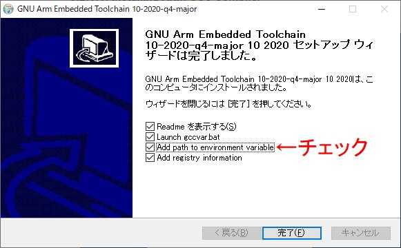
今日は早めで帰宅は18時過ぎ。日曜に秋月電子通商でRaspberry Pi Picoを買ったので、Windows上でサンプルソースのビルドをするべく環境構築を行いました。Getting started with Raspberry Pi Picoの8.2. Building on MS Windowsを読めばできる、とWindowsでのC/C++環境構築 ーRaspberry Pi Picoへの道2ーに書いてあったので、ドキュメントPDFを落としてきてその通りにやってみました。1.ARM GCC CompilerのインストールGNU Arm Embedded Toolchain Downloadsからgcc-arm-none-eabi-10-2020-q4-major-win32.exeをダウンロードしてインストールします。バージョンは変わるかもしれませんが、たぶん大丈夫でしょう。(^^;インストールのときにツールのパスを環境変数に追加するオプションにチェックを入れろ、と書いてあるので、その通りにします。インストールが終わるタイミングですね。オプションにチェックを入れるこれでARMのコンパイラのインストールは完了です。2.CMakeのインストールCMakeからcmake-3.19.4-win64-x64.msiをダウンロードしてインストールします。こちらもバージョン変わるかもしれませんが大丈夫でしょう。CMakeのインストールでもシステムPATHにCMakeを追加するオプションを設定しろ、と書いてあるので、その通りにします。CMakeのインストールオプションインストーラが完了したら CMake のインストールは完了です。3.Visual Studio ? のインストールドキュメント中には Visual Studio Code のインストール、と書いてあるのですが、ダウンロードするのは、ダウンロードのVisual Studio 2019のツールの中にあるBuild Tools for Visual Studio 2019です。ドキュメント中のリンクだけではちょっとわかりにくいな、と思いました。(^^;;これを実行して、C++ によるデスクトップ開発をインストールすればよい、と書いてあります。私の場合は Visual Studio 2019 をインストール済やったので、C++ によるデスクトップ開発はインストール済でした。インストールする場合はココをチェック4.Python 3.7のインストールPython Releases for WindowsからPython 3.7をダウンロードしてインストールすればいいようですが、私の環境には既に Python 3.7 が入ってたので省略しました。Pythonのバージョンが3.7でないとダメなのかは不明です。(^^;;5.gitのインストールDownloading Gitから64-bit Git for Windows Setup.のリンクで git の最新版をダウンロードします。インストールするのですが、ドキュメントにはいくつかオプションをこうしろ、という指示があるので、その通りにします。改行の変換に関するオプションgit bashで使うターミナルエミュレータの設定試行的なオプションの設定インストーラが終了すればインストールは終わりです。---これで、ツール類のインストールは完了です。6.SDKとサンプルの入手SDKとサンプルをダウンロードしたいフォルダに移動して以下をコマンドプロンプトで実行します。git clone -b master https://github.com/raspberrypi/pico-sdk.gitcd pico-sdkgit submodule update --initcd ..git clone -b master https://github.com/raspberrypi/pico-examples.gitこれで今いるフォルダの下にpico-sdkとpico-examplesができます。7.コマンドラインでサンプルをビルドVisual StudioのDeveloper Command Promptを起動します。メニューからだとコレを起動このコマンドプロンプト上で先ほどサンプルをダウンロードしたフォルダに移動します。ここで、setx PICO_SDK_PATH "..¥..¥pico-sdk"を実行します。理由は分かりませんが、ドキュメントにはこのウィンドウを閉じて、別のDeveloper Command Promptを起動しろ、と書いてあるので、その通りにします。またまたサンプルをダウンロードしたフォルダに移動して、以下のコマンドを実行するとpico-examples以下のサンプル全てがビルドされます。cd pico-examplesmkdir buildcd buildcmake -G "NMake Makefiles" ..nmake8.Raspberry Pi Picoへのサンプル書き込みこれでサンプルソースがビルドできたので、buildの下にあるフォルダ内にあるuf2ファイルを Raspberry Pi Pico に書き込めば、そのサンプルが実行されます。Raspberry Pi Pico の白いスイッチを押しながらUSBポートに接続すると、USBデバイスとして認識されて、ドライブとして開くことができるようになります。そのドライブにサンプルの uf2 ファイルをドロップすると、サンプルが書き込まれます。エクスプローラのフォルダにドロップするファイルが書き込まれると自動的にサンプルが走り始めます。blink.uf2を書き込めば Lチカが始まります。---っちゅうことで、公式ドキュメント通りに進めれば Raspberry Pi Pico のサンプルソースをビルドできることが確認できました。picoboard-blinky.uf2 を書き込んだ場合--- 19:40 ---
February 10, 2021
コメント(0)
-

ケーブル延長できる USB DEL キーをdigisparkで作った
今日は晴れ。子ども(弐)用にdigispark + Cherry 青軸でDELキーを作ったのですが、どうもVersaPro VC-JのUSBポートの高さが微妙に高くて、キーを打ったときにボードがしなるのが気になる、ということでした。っちゅうことで、digisparkの USB 直挿しではない方、つまり、USB microB コネクタ付の方をShigezoneで確保して同様の USB DEL キーを作成してみました。Cherry 青軸の端子のはんだ付だけでキーの強度を保つのは厳しそうやったので、キーの下に接着剤を流し込んであります。ただし、キーの真ん中辺は軸が飛び出してくるので、そこには接着剤が流れ込まないようにします。USB microB コネクタ付の USB DELキーこれでケーブルを使えば USB 端子から延長して DEL キーが使えるようになりました。使い勝手がいいのか悪いのかは子ども(弐)に判断してもらいましょう。--- 11:40 ---
November 29, 2020
コメント(0)
-
digispark + Cherry 青軸でDELキーを作った(^^;
今日は早めで帰宅は18時過ぎ。digispark を使ってUSB 'DEL' キーを作ったのですが、なぜか子ども(弐)には受けが悪かったです。「キーはCherryの青軸でないと...」という子ども(弐)のこだわりがあるようです。(^^; メカニカルキーが好きなのかな。っちゅうことで、千石電商でCherry MX-ENN-BC MX青軸1倍キー キートップ付きを買って、前と同様にdigispark を使って USB 'DEL' キーを作ってみました。キーはCherryの青軸今回、基板はaitendoの特価の基板を使いました。Cherryの青軸の端子のピッチは2.54mmではないので、割と無理やり曲げて半田付けしました。(^^;; 他にも端子の横にでっぱりがあるので、これは切断しました。軸が通る部分の保護のようですが、軸が外に飛び出る訳ではないのでヨシとしました。半田面半田面は特に劣化してなかったので半田付けはしやすかったです。その割には仕上がりが汚い... (^^;;キートップを取り付けて完成キートップが付いてたので取り付けて完成です。digisparkのスケッチは全く同一なので省略します。確かに押し心地は良いこの動画のように押すとカチカチ感触があって、押し心地は良いです。この辺が子ども(弐)のこだわりなのでしょう。(^^;;--- 18:40 ---
November 18, 2020
コメント(0)
-
Arduino Nano 互換ボードにPS/2キーボードを接続した
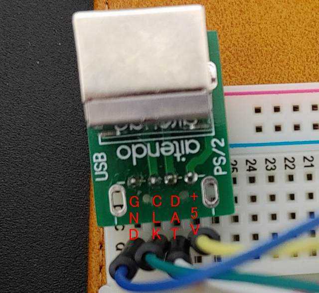
今日は早めで帰宅は18時過ぎ。Shigezoneの激安(300円)版Arduino nano 互換ボードを動かしたで動くようになったArduino Nano互換ボードにPS/2キーボードを接続してキー入力のテストをしてみました。PS/2キーボードをArduino Nanoに接続するためにPS/2のコネクタを取り付けなければならんのですが、USB〜PS/2変換キット [K-UPS2]のUSBコネクタを付けるところにピンヘッダを付けてブレッドボードに挿し、配線を行いました。USB〜PS/2変換キットのピン配置上図のようなピン配置になってます。PS/2キーボードをArduinoで扱うためのライブラリはいくつかあるのですが、Arduino_PS2Keyboardというライブラリを使わせてもらいました。このページの「↓Code」と書いてあるところをクリックしてから「Download ZIP」を押してArduino_PS2Keyboard-master.zipをダウンロードします。このファイルを解凍すると出てくるPS2KeyboardというフォルダをC:¥Program Files (x86)¥Arduino¥librariesの中にコピーします。これでライブラリが使えるようになります。PS/2側 → Arduino NanoGND → GNDCLK → D3 (ホントは10kΩぐらいで+5Vにプルアップする)DAT → D8 (ホントは10kΩぐらいで+5Vにプルアップする)+5V → +5Vのように接続して、以下のスケッチを動かすと、PS/2キーボードで打った文字が液晶上に表示されます。液晶(ST7032)とArduino Nanoとの結線はaitendoのI2C/SPI両用キャラクタ液晶を組み立てたの通りに行います。#include <Wire.h>#include <ST7032.h>#include <PS2Keyboard_stm32.h>const int DataPin = 8;const int IRQpin = 3;PS2Keyboard keyboard;ST7032 lcd;int x, y;void setup() { // put your setup code here, to run once: keyboard.begin(DataPin, IRQpin); lcd.begin(16,2); lcd.setContrast(60); lcd.clear();}void loop() { char c; // put your main code here, to run repeatedly: if (keyboard.available()) { c = keyboard.read(); lcd.setCursor(x, y); lcd.write(c); x++; if (x > 15) { x = 0; y++; if (y > 1) { y = 0; } } }}PS/2キーボードの入力が液晶に表示される写真ではわかりにくいので、動画も撮ってみました。PS/2キーボード入力→液晶の動画これで、Arduino Nano単体でキーボード入力できることが確認できました。これは一応、前振りの予定。(^^;--- 18:45 ---
November 12, 2020
コメント(0)
-
Shigezoneの激安(300円)版Arduino nano 互換ボードを動かした
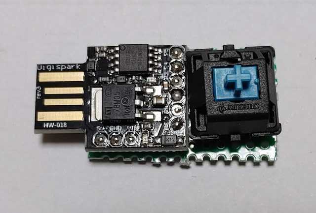
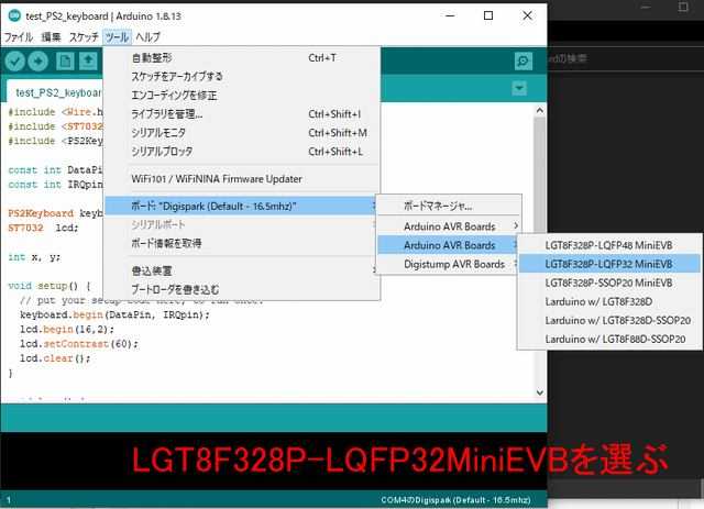
今日は早めで帰宅は18時過ぎ。子ども(壱)が大学のリモート授業で使ってるdynabookの液晶を割ってしまったようです。(^^; 大学指定機種で生協で買ったのである程度の保証はあるようなのですが... 緊急措置として授業を受けるのに嫁はんのVersaPro VC-Mを使ってるようです。---Shigezoneで[激安版] Arduino Nano互換ボードLGT8F328Pを買っておいたので、使ってみることに。普通の(?)互換ボードはUSB端子がminiBらしいのですが、Shigezoneの激安互換ボードのUSB端子はmicroBです。地味にうれしい。互換品やからArduino IDE でボードをArduino Nanoを選んでスケッチを書き込めば動くんやろう、と思ってたら甘かったです。(^^;; ボードが返事しないよ、みたいなエラーが出て書き込めません。やっぱりCPU自体が互換品(LGT8F328P)なのでボード情報などをArduino IDEに教えてやらないと認識してくれないようです。Google先生にLGT8F328Pで訊いてみると、LGT8f328P Arduino互換ボードを使ってみるというページにたどり着きました。このページに書いてあるように、ダウンロードページの一番下にあるLarduino_HSP_latest.rarをダウンロードします。このrarファイルを解凍すると、hardware、libraries、sketchesの3つのフォルダとinstall.txtが出てきます。 install.txt に書いてある通り、hardwareとlibrariesをC:¥Program Files (x86)¥Arduinoの下のhardwareとlibrariesの下にコピーすればよいようですが、hardwareの中にあるpackage_index_bundled.jsonとplatform.keys.rewrite.txtは上書きしたくなかったので、hardwareの中にあるLGTというフォルダだけhardwareの中にコピーしました。librariesの方は全部のフォルダをコピーしても重複は無かったので大丈夫そうです。これで、Arduino IDEの[ツール][ボード]からたどって、LGT8F328P-LQFP32MiniEVBをボードとして選べば、スケッチを書き込めるようになりました。LGT8F328P-LQFP32MiniEVBを選ぶ試しにaitendoのI2C/SPI両用キャラクタ液晶を組み立てたで使った結線とスケッチを使って実行したのが下の写真です。aitendoのI2C液晶を駆動するスケッチを実行ピン数は少ないですが、Arduino Unoより小さくてブレッドボード1枚に色々収めることができるので便利そうです。今度Shigezoneに行ったときに[激安版] Arduino Nano互換ボードLGT8F328Pを何枚か買っておこう。ピンヘッダが付属してるとなおよいのですが、価格的には難しいかな。(^^;;--- 19:10 ---
November 9, 2020
コメント(0)
-
aitendoのI2C/SPI両用キャラクタ液晶を組み立てた
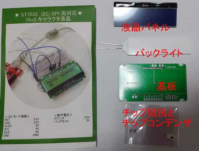
今日は晴れ。aitendoの移転セール(11月)で I2C/SPI両用液晶モジュール(16x2) [G1812M2] が特価350円で売ってたので2つ買いました。この商品、モジュール、と書いてありますが、自分で組み立てる必要がありました。(^^;G1812M2の中身液晶モジュール、LEDバックライトモジュール、取付用の基板、チップ抵抗1つとチップコンデンサ2つ、が入ってました。これを順に基板に取り付けていきます。まずはチップ部品からまずはチップ抵抗とチップコンデンサを取り付けます。1608サイズぐらいの部品でランドも余裕をもって作ってあるので、老眼で見えないのを除けば(^^)、そんなに難易度は高くありませんでした。ランドに予備はんだを少ししておくのがよいようです。次はLEDバックライトモジュール次にLEDバックライトモジュールを取り付けます。A(アノード), K(カソード)と書かれたランドはありますが、部品面からこのランドにリード線を通すのではなく、裏面にリード線を折り曲げてはんだ付けするような格好になります。どっちのリード線がアノードなのかカソードなのか覚えてない(長さで決まってるはず)ので、実際に5Vをかけてみて光る面を上になるようにして取り付けました。(^^;; 取り付ける前に液晶パネルをはめてみて、バックライトがちゃんと液晶面にくるように確認しておいた方がいいでしょう。液晶パネルをはんだ付け最後の部品は液晶パネルです。ピンをランドに挿し込んではんだ付けするだけです。また、私はI2C接続の液晶として使いたかったので、I2Cと書かれた方のランドをはんだで短絡させました。ヘッダピンは付属してないブレッドボードに挿して使いたかったので、手持ちのヘッダピンを取り付けました。以上で液晶モジュールの組み立ては完了です。この液晶モジュールはコントローラICがST7032が使われているので、aitendoのG1812M2のページの下の方に書いてあるように、I2C液晶のArduinoライブラリ – ST7032を使わせてもらいました。Arduino UNO互換ボードとの接続もG1812M2のページの下の方に書いてあるように行います。テストに使用したスケッチ#include <Wire.h>#include <ST7032.h>ST7032 lcd;int chr = 0x20;int cnt = 0;void setup() { // put your setup code here, to run once: lcd.begin(16,2); lcd.setContrast(60); lcd.print("Hello, world!");}void loop() { // put your main code here, to run repeatedly: lcd.setCursor(0,1); lcd.print(cnt++); lcd.setCursor(15,0); lcd.write(chr); chr = (++chr > 256) ? 0x20 : chr; delay(1000);}スケッチを実行するとこんな感じで表示されます。テストスケッチを実行中上段右端には0x20以上の内蔵キャラクタを表示しています。カタカナもキャラクタとしては存在してるようです。っちゅうことで、aitendoの16x2のI2Cキャラクタ液晶G1812M2がちゃんと動作することが確認できました。--- 13:45 ---
November 8, 2020
コメント(0)
-

aitendo特価99円の液晶モジュールを動かしてみた
今日は曇り。aitendoが12月に店舗を移転するので、11月中は店舗で移転セールをやってます。店内の品物20%引。その他、特価品が色々売ってました。その中で、 ★特売品★キャラクタ液晶モジュール(16文字x1行) [WD-A1601M] っちゅうのが、箱にいっぱいあったので、2つばかり買ってみました。詳細不明、っちゅうことですが、端子は16ピンです。WD-A1601Mのピン配置これはパラレル接続(?)の液晶のピン配置と似ているなぁ、っちゅうことで、1番ピン:VSS2番ピン:VDD3番ピン:V04番ピン:RS5番ピン:R/W6番ピン:Enable7番ピン:DB08番ピン:DB19番ピン:DB210番ピン:DB311番ピン:DB412番ピン:DB513番ピン:DB614番ピン:DB715番ピン:NC16番ピン:NCと予想して、Shigezoneで買ったArduino Uno互換ボードにLCDを接続してみたと同様にArduino互換ボードに配線して、スケッチを動かしてみました。コネクタのどこが1番ピンかはテスタで確認してください。(^^;すると、あっさり文字表示することができました。hello, world!を表示っちゅうことで、WD-A1601Mはバックライトは無いものの16x1表示の液晶として使えることが分かりました。コネクタが付いてて配線しやすいのがいいですね。16x1でいいから安い液晶表示器が欲しい方はaitendoの移転セールで!--- 14:55 ---
November 7, 2020
コメント(0)
-
Sourcetreeを使ってLonganNanoのソースファイルをGitHubで管理するようにした
今日は晴れて清々しい。Longan Nano のシリアル通信に色々トライしていますが、ソースファイルを公開しやすくするため、GitHubで管理したいなぁ、と思いました。Windows上でGitをコマンドラインで使うのも何かめんどくさそうなので、何かGUIはないかなぁ、と探していたら、Sourcetreeというツールがあるのが分かりました。っちゅうことで、GitHubとSourceTreeの連携とプッシュ・プル操作とか簡単Git入門02 ローカルファイルをリポジトリとして指定するなど色々なところを参考に、Sourcetreeをインストール、Longan Nanoのプロジェクトのソースフォルダをローカルリポジトリに指定して GitHubにソースファイルをプッシュするところまでできました。変更したファイルをコミットしてプッシュ、という単純な作業しかしてませんが、コマンドラインで操作するよりはだいぶ楽な気がします。本格的なところはコマンドラインでやらないといけないのかもしれませんが... (^^;っちゅうことで、GitHub上に2つのリポジトリを作成しました。GitHub上のLongan Nano シリアル受信サンプル1キャラクタをシリアル受信して、Longan Nanoの画面に表示するとともに、端末側にエコーバックするソースファイルです。GitHub上のLongan Nano シリアル受信サンプル(DMA使用)16キャラクタをシリアル受信したらDMA転送で読み込むソースファイルです。結果はLongan Nanoの画面と端末側に表示されます。まだバグとか分からないことがありますが、とりあえず情報共有っちゅうことで。(^^;;--- 12:10 ---
October 25, 2020
コメント(0)
-
Longan Nanoの USART で DMA を使おうとしているが...
今日は早めで帰宅は18時過ぎ。Longan Nano の USART を試してみたときに、usart_data_receive(USART0)で一度データを読み込んでしまうと、リードバッファが空でないフラグがリセットされてしまい、TeraTermなどからファイル送信したデータは最初の1文字しか読めない、っちゅうことが分かりました。GD32VF103 User ManualのUSARTの項目を見ても、The RBNE bit is cleared by a read operation on the USART_DATA register, whatever it is performed by software directly, or through DMA.「ソフトウェアから直接でも、DMA転送によってでもUSART_DATAレジスタを1回読む動作をするとRBNEビットはクリアされます。」と書いてあるので、仕方ないことのようです。ただし、DMA転送で読んだときはどのように読めるのかはやってみなければ分からないので、試してみることにしました。まだ途中段階ですが、(1) rcu_periph_clock_enable(RCU_DMA0);でDMA0に電源を供給する(←ココ大事!!)(2) dma_parameter_structっちゅう型の構造体にパラメータをセットしてDMAパラメータの初期化をする(DMA0のチャネル4がUSART0に対応するらしい)(3) DMA割込をセットする(4) USART0の割込をセットする(4) usart_dma_receive_config(USART0, USART_DENR_ENABLE)でUSART0でDMAを使う設定にする(5) USART0の割込フラグが立ったら、DMA転送を有効にする(6) DMA転送フラグが終了になったら、転送先の配列にデータが格納される(7) DMA転送フラグをクリアする(8) DMA転送を無効にする(9) DMAパラメータの初期化をする(10) (5)~(9)をぐるぐる回るといった概略の流れでDMA転送によるUSART0の受信はできたように見えます。まだ、先頭文字が欠けたり化けたり、とか色々謎な現象は起きているのですが、DMA転送できているのは確かです。ただ、DMA転送を有効にすると指定した転送バイト数に達するまで(USART受信バッファに必要バイト数のデータが溜まるまで)転送が終わらない、っちゅう難点もあります。(^^; まぁ、そらそやわな。っちゅうことで、DMA転送によるUSART受信に果たして価値があるのか悩んでいるところです... (^^;;--- 20:15 ---
October 15, 2020
コメント(0)
-

Longan Nano の USART を試してみた
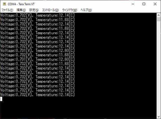
今日は晴れ時々曇り。ShigezoneでLongan NanoをPCにシリアル接続するためのUSB-シリアル変換器を買ったので、Longan Nano を PCに接続して USART を試してみました。Longan Nano と USB-シリアル変換器の接続は、R0 <--> TXDT0 <--> RXDGND <--> GNDのようにRX/TXをクロスに接続するだけです。制御線を使ってないから実際はUART通信になります。Longan NanoとUSB-シリアル変換器の接続Longan Nano の USART によるPCへの文字出力(USARTの送信)については、久しぶりにLongan Nanoを参考にさせて(パクらせて(^^))いただきました。受信については記述してるページがほとんど無いので、.platformio¥packages¥framework-gd32vf103-sdk¥GD32VF103_standard_peripheral¥Sourceにあるgd32vf103_usart.cを見たら、USARTの割込有効化(usart_interrupt_enable)、USARTの割込フラグ取得(usart_interrupt_flag_get)、USARTからの受信(usart_data_receive)の関数があることが分かりました。使い方としては、usart_interrupt_enable(USART0, USART_INT_FLAG_RBNE);でUSART0の受信バッファが空でないことを示す割込をイネーブルにして、usart_interrupt_flag_get(USART0, USART_INT_FLAG_RBNE) == SETUSART0の当該割込がセットされてる間に、c = usart_data_receive(USART0);USART0からデータを読み込めばよい(らしい)ということが何となく分かりました。どっか間違ってる可能性もあるのですが...っちゅうことで、久しぶりにLongan Nanoでコピーしてるサンプルプログラムのソースがプロジェクトフォルダにあるのを前提に下記のソース(main.c)をコンパイルしてLongan Nano に書き込んでみました。#include "lcd/lcd.h"#include "gd32v_pjt_include.h"#include <stdio.h>#include <string.h> void init_uart0(void){ /* enable GPIO clock */ rcu_periph_clock_enable(RCU_GPIOA); /* enable USART clock */ rcu_periph_clock_enable(RCU_USART0); /* connect port to USARTx_Tx */ gpio_init(GPIOA, GPIO_MODE_AF_PP, GPIO_OSPEED_50MHZ, GPIO_PIN_9); /* connect port to USARTx_Rx */ gpio_init(GPIOA, GPIO_MODE_IN_FLOATING, GPIO_OSPEED_50MHZ, GPIO_PIN_10); /* USART configure */ usart_deinit(USART0); usart_baudrate_set(USART0, 115200U); usart_word_length_set(USART0, USART_WL_8BIT); usart_stop_bit_set(USART0, USART_STB_1BIT); usart_parity_config(USART0, USART_PM_NONE); usart_hardware_flow_rts_config(USART0, USART_RTS_DISABLE); usart_hardware_flow_cts_config(USART0, USART_CTS_DISABLE); usart_receive_config(USART0, USART_RECEIVE_ENABLE); usart_transmit_config(USART0, USART_TRANSMIT_ENABLE); usart_enable(USART0); // usart_interrupt_enable(USART0, USART_INT_RBNE);} int main(void) { uint16_t c; u8 x = 0, y = 0; // LED output setting rcu_periph_clock_enable(RCU_GPIOA); rcu_periph_clock_enable(RCU_GPIOC); gpio_init(GPIOC, GPIO_MODE_OUT_PP, GPIO_OSPEED_50MHZ, GPIO_PIN_13); gpio_init(GPIOA, GPIO_MODE_OUT_PP, GPIO_OSPEED_50MHZ, GPIO_PIN_1|GPIO_PIN_2); // initialize USART0 init_uart0(); // initialize OLED Lcd_Init(); // lights LEDs LEDR(1); LEDG(1); LEDB(1); // clear OLED LCD_Clear(BLACK); // enable read buffer not empty interrupt flag of USART0 usart_interrupt_enable(USART0, USART_INT_FLAG_RBNE); while (1) { // if read buffer is not empty if (usart_interrupt_flag_get(USART0, USART_INT_FLAG_RBNE) == SET) { // while read buffer is not empty while (usart_interrupt_flag_get(USART0, USART_INT_FLAG_RBNE) == SET) { // read character from USART0 c = usart_data_receive(USART0); // put character to USART0 (echo back) _put_char((u8)c); // put character to OLED LCD_ShowChar(x, y, (u8)c, 1, WHITE); // cursor control x += 8; if (x > 18 * 8) { x = 0; y += 16; if (y > 4 * 16) { LCD_Clear(BLACK); y = 0; } } } // if read buffer is empty } else { // flip LEDs LEDR_TOG; delay_1ms(20); LEDG_TOG; delay_1ms(20); LEDB_TOG; delay_1ms(20); } }}// put a character to USART0int _put_char(int ch){ usart_data_transmit(USART0, (uint8_t) ch ); while ( usart_flag_get(USART0, USART_FLAG_TBE)== RESET){ } return ch;} #include <stdarg.h>void usart_printf(const char *fmt, ...) { char buf[100]; va_list args; va_start(args, fmt); vsprintf(buf, fmt, args); va_end(args); char *p = buf; while( *p != '\0' ) { _put_char(*p); p++; }}上記ソースコードで実現してるのは、PC上のターミナルソフトから入力した文字をLongan NanoのOLED上に表示すると共にターミナルソフトにエコーバックする、っちゅう機能です。一応、ターミナルソフトからポチポチ入力した文字はOLEDに表示され、ターミナルソフトにエコーバックされるのですが、ターミナルソフトからファイル送信した文字列がうまく表示できません。受信バッファの最初に一文字しか読めてない感じです。割込が起きたときに受信バッファを一旦まとめてどっかに読みだしてそれからポチポチ表示なりエコーバックする必要があると思うのですが、受信割込とか受信バッファに関する情報が無く、手詰まりな状態です...Longan Nano の USART 受信ができたとはいえ、まだまだちゃんとしたモノにはなってないので、何とかせんといかんなぁ。--- 16:00 ---
October 11, 2020
コメント(0)
-
digispark を使ってUSB 'DEL' キーを作った
今日は曇り時々晴れで秋らしい。DELキーのキートップが欠損している mouse Pro NB370H (Core i5 5200U 2.2GHz, メモリ8GB, SSD)の DEL キーの代わりとなるデバイスを作ろうと、こないだShigezoneで digispark 互換品を 0.25千円で、千石電商で大きめのタクトスイッチとキートップを買ってきました。NB370HのDELキー、キートップが欠損しててもDELキーとしては機能するのですが、まぁ、そこは置いといて... (^^;digispark にピンヘッダを半田付けして、P0とGNDの間にタクトスイッチをかましただけの回路をユニバーサル基板の切れ端を使って作成しました。半田面:ちょっと強引な配線ユニバーサル基板のランドが酸化してて半田付けしにくかったです。(^^;; かなり汚い半田付けになってしまいました...部品面:コンパクトにできた部品のサイズきちきちで作ったのでだいぶコンパクトにまとまりました。Arduino開発環境を使って以下のスケッチをコンパイルしてdigisparkに書き込みます。#include <DigiKeyboard.h>#define PIN_DEL 0#define KEY_DEL 0x4Cvoid setup() { // put your setup code here, to run once: pinMode( PIN_DEL, INPUT_PULLUP );}void loop() { // put your main code here, to run repeatedly: unsigned char pdel; DigiKeyboard.sendKeyStroke(0); pdel = digitalRead( PIN_DEL ); DigiKeyboard.update(); if (pdel == LOW) { DigiKeyboard.sendKeyStroke( KEY_DEL ); } DigiKeyboard.delay(200);}P0をプルアップ付の入力に設定し、タクトスイッチが押されてGNDに接続されたら(LOWになったら)、DELキーのキーコードを送る、というだけの内容です。digisparkに書き込むとき、USBポートによっては正常に認識されないことがあり、難儀しました。(^^;; さて、NB370HにUSB 'DEL' キーを接続してみましょう。NB370Hに接続したところ最初接続してみたら、基板下に出っ張ってたピンヘッダのピンが若干邪魔だったので、短くカットしました。これでちょうどよい具合になりました。他のUSBデバイスとも干渉しないUSBマウスと並べて挿してみましたが、コンパクトに作ったおかげで干渉することなく使用できました。USB 'DEL' キーのデモちょっと分かりにくいですが、こんな感じでDELキーの代わりとして使うことができます。ボタンを押すと基板が少ししなるので、PCのUSB端子にちょっと負担がかかりそうな感じもします。(^^;;まぁ、とりあえずはUSB接続のDELキーができた、っちゅうことで。--- 15:15 ---
September 26, 2020
コメント(0)
-
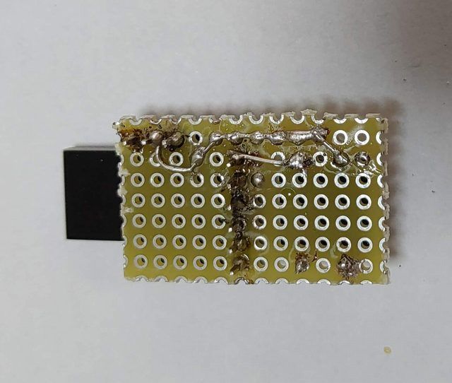
Tang Nano の開発環境を整えた
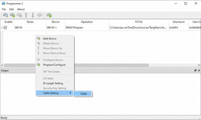
今日は晴れて、そこそこ暑い。前の週末にShigezoneで買った0.8千円の激安FPGAボード、Tang Nanoの開発環境を整えました。っちゅうても、SiPeed Tang Nanoの環境構築(Windows編)を参考に開発ツールのセットアップをしただけですが... (^^; ただし、分かったことも幾つかあります。(1) 最新版の開発ツールではSRAM/FlashともにFPGAへの書き込みができない(Unknown Cableというエラーが出る)。(2) 旧バージョン(V1.9.3.02Beta)でもケーブル設定を適切にしないとFPGAのFlashへの書き込みができない。(1)は参考にしたページにも書かれてたことなのですが、もっと新しいバージョンならいけるかも?とV1.9.6.02Betaをダウンロードして試してみたのですが、FPGAへの書き込み時にUnknown Cableというエラーが出て書き込みができません。SRAMへの書き込み、Flashへの書き込みいずれも同じエラーが出ます。っちゅうことで、(2)のように旧バージョン(V1.9.3.02Beta)をインストールしなおして、FPGAへの書き込みを試してみました。SRAMへの書き込みでは問題なく書き込めたのですが、FPGAのFlashROMに書き込もうとしたら、書き込みプロセスが進みません... orz設定で変えられるところはないかと色々探したところ、ケーブル設定が変えられそうです。プログラマでケーブル設定を選択上記のCableを選ぶとケーブル設定が開きます。ケーブル設定ここで、Portとして最初はGowin USB Cable (FT2CH)/0/B というのが選択されてたのですが、上図のようにGowin USB Cable (FT2CH)/1/Aに変更すると SRAM書き込みができるようになりました!が、FlashROMへの書き込みを行うと書き込み動作が終わった後に、Error Finished, NOT wakes upっちゅうエラーが出て書き込みができません... orz Verifyオプションを付けて書き込んでみるとVerifyエラーが出るので、正しく書き込まれていない様子。っちゅうことで、上記エラーでGoogle先生に訊いてみると、Sipeed Tang Nano を使ってみる。No.5 最新Toolで書き込めない原因判明っちゅうページを発見。ここに書かれているように、Frequency を 2.5MHzにしたらFlashROMへの書き込みもできるようになりました。Frequency設定を変える以上のように、最新版でないツールを使ってもハマりどころが色々あるので、注意しましょう。(^^;;一応、書き込みはできて、(元とは違う)Lチカができるようになりました。動作中のTang Nano--- 13:35 ---
September 5, 2020
コメント(0)
-

Longan Nanoの開発環境を整備した
今日は晴れて暑い。昨日、Shigezoneで買った Longan Nano の開発環境を整備しました。っちゅうても、Longan Nano 爆速Tips - 環境設定~Lチカ編 -を参考に PlatformIO をVScodeにインストールして設定をしただけです。ただし、デバイスの認識で問題があるので、そのことだけ書いておきます。上記ページにある/LONGAN/Nano/ToolsからダウンロードしたGD32_MCU_Dfu_Tool_V3.8.1.5784_1.rarを解凍してドライバをインストールするのは問題なく実行できました。これでDFUモードに入る、1.BOOTボタンを押す2.RESETボタンを押す3.RESETボタンを離す4.BOOTボタンを離すとデバイスとしては、GD32 Device in DFU Modeとして認識されます。GD32 Device in DFU Modeとして認識されるこの状態でドライバに同梱されているツールからデバイスが見えるようになります。ツールでデバイスが認識される参考にしたページでは、ドライバをzadigで置き換えるような記述があるので、zadig-2.4で試してみましたが、デバイスが認識されません。zadig-2.5だと認識される(デバイス名が空欄なので怪しいのですが...)のですが、ドライバを置き換えようとするとエラーが出て置き換えることができませんでした。っちゅうことで、PlatformIOからコンパイルしたファイルを Longan Nano に転送しようとすると、デバイスがちゃんと認識されていないので、Cannot open DFU device 28e9:0189No DFU capable USB device availableっちゅうエラーが出てバイナリファイルの転送に失敗します。転送に失敗するドライバに同梱されているツールでバイナリファイルをLongan Nanoに転送して書き込むことはできるので、いいといえばいいのですが... ちとめんどくさい。(^^;っちゅうことで、コンパイルはPlatformIOで、転送はツールでという変則的な開発環境ですが、とりあえず Longan Nano の開発ができるようにはなりました。---書込ができるようになったので、Longan nano で Hello World!を参考に液晶に Hello World! を表示して、ランダム直線とランダム四角形(塗りつぶし)を描画するプログラムを作ってみました。ケースに入れたLongan Nanoテストプログラムの動作する様子こうして見ると直線の描画も塗りつぶし四角形も結構な速度で描画できているのが分かります。Longan Nanoはナカナカ高性能なボードのようです。これが750円で買えるんやからスゴイねー。--- 17:50 ---
August 9, 2020
コメント(0)
-
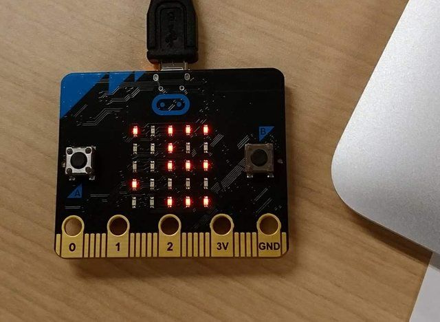
子ども(弐)がプログラミング入門講座に行った
今日は曇りでそんなに暑くなかった。子ども(弐)がプログラミングに興味があるっちゅうことで、お試しでプログラミング入門講座に行ってみました。プログラミング、っちゅうことで、何らかの言語でちょこちょこプログラムを作るのかと思いきや、micro:bitを使って、フィジカルなモノのプログラミングをする講座でした。MakeCodeエディタを使って、Scratchのように視覚的にプログラミングができるようになっていたので、子ども(弐)も講師のチュートリアルが終わる頃には大体の雰囲気が分かったようです。その後、60分程で好きなようにプログラミングをしてください、とのことやったので、子ども(弐)もプログラミングにチャレンジ。micro:bitで何やら作ったらしい子ども(弐)はmicro:bitに載ってるセンサ類が気になったみたいで、照度センサや加速度センサを使って表示を変えたりするプログラムを作ったようです。他の参加者の中には音を出したりしてる人もいたみたいです。子ども(弐)もmicro:bitのプログラミングは面白かったようで、これなら遊べる、と言ってました。某ワンクリックなとこで調べても、2千円程度で買えるようなので買ってみるのもいいかも。(^^;--- 19:20 ---
August 24, 2019
コメント(0)
全211件 (211件中 1-50件目)