
- Dataset Availability
- 1984-04-07T10:04:11Z–2013-01-01T16:51:58Z
- Dataset Provider
- USGS
- Revisit Interval
- 16 Days
- Tags
Description
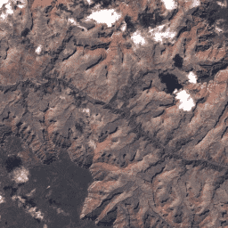
Landsat 5 MSS Collection 2 Tier 1 DN values, representing scaled, calibrated at-sensor radiance.
Landsat scenes with the highest available data quality are placed into Tier 1 and are considered suitable for time-series processing analysis. Tier 1 includes Level-1 Precision Terrain (L1TP) processed data that have well-characterized radiometry and are inter-calibrated across the different Landsat sensors. The georegistration of Tier 1 scenes will be consistent and within prescribed tolerances [<=12 m root mean square error (RMSE)]. All Tier 1 Landsat data can be considered consistent and inter-calibrated (regardless of sensor) across the full collection. See more information in the USGS docs .
Bands
Bands
B1
Green
B2
Red
B3
Near Infrared 1
B4
Near Infrared 2
QA_PIXEL
Landsat Collection 2 MSS QA Bitmask
QA_RADSAT
Radiometric saturation QA
Image Properties
Image Properties
Percentage cloud cover (0-100), -1 = not calculated.
Percentage cloud cover over land (0-100), -1 = not calculated.
Tier of scene. (T1 or T2)
Number of collection.
Internal calibration gain method for band 1.
Internal calibration gain method for band 2.
Internal calibration gain method for band 3.
Internal calibration gain method for band 4.
Indicates the source of the DEM used in the correction process. Possible values: "GLS2000", "RAMP", "GTOPO30".'
Data type identifier string used to create the L0RP product.
Image acquisition date. "YYYY-MM-DD"
Product generation epoch.
Datum used in image creation.
Earth sun distance in astronomical units (AU).
Ellipsoid used in image creation.
Ephemeris data type used to perform geometric correction. (Definitive or Predictive)
Gain state for Band 1. (L = Low gain, H = High)
Gain state for Band 2. (L = Low gain, H = High)
Gain state for Band 3. (L = Low gain, H = High)
Gain state for Band 4. (L = Low gain, H = High)
Combined Root Mean Square Error (RMSE) of the geometric residuals (meters) in both across-track and along-track directions measured on the GCPs used in geometric precision correction. Not present in L1G products.
RMSE of the X direction geometric residuals (in meters) measured on the GCPs used in geometric precision correction. Not present in L1G products.
RMSE of the Y direction geometric residuals (in meters) measured on the GCPs used in geometric precision correction. Not present in L1G products.
RMSE of the geometric residuals (pixels) in both line and sample directions measured on the terrain-corrected product independently using GLS2000.
RMSE of the geometric residuals (pixels) of the lower-left quadrant measured on the terrain-corrected product independently using GLS2000.
RMSE of the geometric residuals (pixels) of the lower-right quadrant measured on the terrain-corrected product independently using GLS2000.
RMSE of the geometric residuals (pixels) of the upper-left quadrant measured on the terrain-corrected product independently using GLS2000.
RMSE of the geometric residuals (pixels) of the upper-right quadrant measured on the terrain-corrected product independently using GLS2000.
Grid cell size used in creating the image for the reflective band.
The number of ground control points used. Not used in L1GT products. Values: 0 - 999 (0 is used for L1T products that have used Multi-scene refinement).
The number of ground control points used in the verification of the terrain corrected product. Values: -1 to 1615 (-1 = not available)
The number of ground control points used in the verification of the terrain corrected product. Values: -1 to 1615 (-1 = not available)
Image quality, 0 = worst, 9 = best, -1 = quality not calculated
The naming convention of each Landsat Collection 1 Level-1 image based on acquisition parameters and processing parameters.
Format: LXSS_LLLL_PPPRRR_YYYYMMDD_yyyymmdd_CC_TX
- L = Landsat
- X = Sensor (O = Operational Land Imager, T = Thermal Infrared Sensor, C = Combined OLI/TIRS)
- SS = Satellite (08 = Landsat 8)
- LLLL = Processing Correction Level (L1TP = precision and terrain, L1GT = systematic terrain, L1GS = systematic)
- PPP = WRS Path
- RRR = WRS Row
- YYYYMMDD = Acquisition Date expressed in Year, Month, Day
- yyyymmdd = Processing Date expressed in Year, Month, Day
- CC = Collection Number (01)
- TX = Collection Category (RT = Real Time, T1 = Tier 1, T2 = Tier 2)
The Pre-Collection naming convention of each image is based on acquisition parameters. This was the naming convention used prior to Collection 1.
Format: LXSPPPRRRYYYYDDDGSIVV
- L = Landsat
- X = Sensor (O = Operational Land Imager, T = Thermal Infrared Sensor, C = Combined OLI/TIRS)
- S = Satellite (08 = Landsat 8)
- PPP = WRS Path
- RRR = WRS Row
- YYYY = Year of Acquisition
- DDD = Julian Day of Acquisition
- GSI = Ground Station Identifier
- VV = Version
Projection used to represent the 3-dimensional surface of the earth for the Level-1 product.
L0RA map projection selectively applied to HDTs based on geographic location. Used for processed archive data.
Orientation used in creating the image. Values: NOMINAL = Nominal Path, NORTH_UP = North Up, TRUE_NORTH = True North, USER = User
Presence of Band 1 (Y = Yes, N = No, M = Missing, I = Unknown)
Presence of Band 2 (Y = Yes, N = No, M = Missing, I = Unknown)
Presence of Band 3 (Y = Yes, N = No, M = Missing, I = Unknown)
Presence of Band 4 (Y = Yes, N = No, M = Missing, I = Unknown)
One of L1GS, L1GT, or L1TP.
Name and version of the processing software used to generate the L1 product.
Additive rescaling factor used to convert calibrated DN to radiance for Band 1.
Additive rescaling factor used to convert calibrated DN to radiance for Band 2.
Additive rescaling factor used to convert calibrated DN to radiance for Band 3.
Additive rescaling factor used to convert calibrated DN to radiance for Band 4.
Multiplicative rescaling factor used to convert calibrated Band 1 DN to radiance.
Multiplicative rescaling factor used to convert calibrated Band 2 DN to radiance.
Multiplicative rescaling factor used to convert calibrated Band 3 DN to radiance.
Multiplicative rescaling factor used to convert calibrated Band 4 DN to radiance.
Additive rescaling factor used to convert calibrated Band 1 DN to reflectance.
Additive rescaling factor used to convert calibrated Band 2 DN to reflectance.
Additive rescaling factor used to convert calibrated Band 3 DN to reflectance.
Additive rescaling factor used to convert calibrated Band 4 DN to reflectance.
Multiplicative factor used to convert calibrated Band 1 DN to reflectance.
Multiplicative factor used to convert calibrated Band 2 DN to reflectance.
Multiplicative factor used to convert calibrated Band 3 DN to reflectance.
Multiplicative factor used to convert calibrated Band 4 DN to reflectance.
Number of product lines for the reflective bands.
Number of product samples for the reflective bands.
Request id, nnnyymmdd0000_0000
- nnn = node number
- yy = year
- mm = month
- dd = day
Resampling option used in creating the image.
Flag indicating saturated pixels for band 1 ('Y'/'N')
Flag indicating saturated pixels for band 2 ('Y'/'N')
Flag indicating saturated pixels for band 3 ('Y'/'N')
Flag indicating saturated pixels for band 4 ('Y'/'N')
Scene center time of acquired image. HH:MM:SS.SSSSSSSZ
- HH = Hour (00-23)
- MM = Minutes
- SS.SSSSSSS = Fractional seconds
- Z = "Zulu" time (same as GMT)
Sensor used to capture data.
Spacecraft identification.
Ground Station/Organisation that received the data.
Sun azimuth angle in degrees for the image center location at the image center acquisition time.
Sun elevation angle in degrees for the image center location at the image center acquisition time.
UTM zone number used in product map projection.
The WRS orbital path number (001 - 251).
Landsat satellite WRS row (001-248).
World Reference System (WRS) type used for the collection of this scene.
Terms of Use
Terms of Use
Landsat datasets are federally created data and therefore reside in the public domain and may be used, transferred, or reproduced without copyright restriction.
Acknowledgement or credit of the USGS as data source should be provided by including a line of text citation such as the example shown below.
(Product, Image, Photograph, or Dataset Name) courtesy of the U.S. Geological Survey
Example: Landsat-7 image courtesy of the U.S. Geological Survey
See the USGS Visual Identity System Guidance for further details on proper citation and acknowledgement of USGS products.
Explore with Earth Engine
Code Editor (JavaScript)
 var

 dataset

 =

 ee
 .
 ImageCollection
 (
 'LANDSAT/LM05/C02/T1'
 )

 .
 filterDate
 (
 '1985-01-01'
 ,

 '1989-12-31'
 );
 var

 nearInfrared321

 =

 dataset
 .
 select
 ([
 'B3'
 ,

 'B2'
 ,

 'B1'
 ]);
 var

 nearInfrared321Vis

 =

 {};
 Map
 .
 setCenter
 (
 6.746
 ,

 46.529
 ,

 6
 );
 Map
 .
 addLayer
 (
 nearInfrared321
 ,

 nearInfrared321Vis
 ,

 'Near Infrared (321)'
 );