全33件 (33件中 1-33件目)
1
-

Structured Fiber Cabling Solutions for Network & Server Cabinet
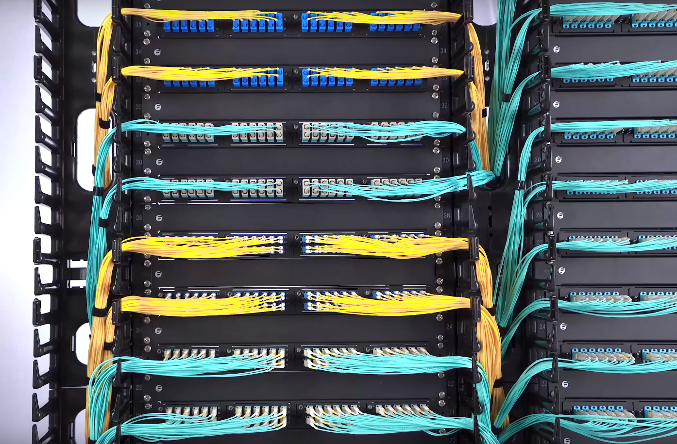
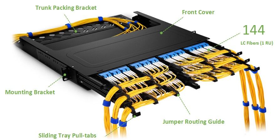
How does your network or server cabinet look like? Are they stocked with varied servers or networking equipment connected with long cables that reach out to the devices on the other cabinet or enclosure? This is exactly what we used to call point-to-point cabling. However, it is also an art to keep a neat cabling. This article unveils a compelling new cabling method—structured fiber cabling solutions for network&server cabinet.What Is Structured Cabling and How Does It Matter?In recent years it has become apparent that fiber-optics are replacing copper wire as an appropriate means of communication signal transmission. The standardized architecture and components for communications cabling formulated by the EIA/TIA TR42 committee—structured cabling is used as a voluntary standard by manufacturers to ensure fiber-optics interoperability. In a structured cabling system, a variety of patch panels and trunk cables are harnessed to create a structure that allows for hardware ports to be connected to a patch panel at the top of the server rack. That patch panel is then connected to another patch panel via a trunk (multi-fiber assembly designed for use in conveyance) in the MDA (Main Distribution Area). When you have several servers, with multiple patch connections and power cords running through your server rack, you need to keep them arranged and managed with an excellent rack cable management system. Here some may wonder why bother to cost more on the connecting gadgets? Well, without running long patch cords from equipment racks, MACs are much quicker as the cable and port tracing becomes a much easier job. The potential for downtime goes down with the reduced potential for human error. A structured cabling system will look aesthetically pleasing.Structured Fiber Cabling Solutions for Network & Server CabinetIn the server room, there may be a server cabinet and a network cabinet for the storage of routers, patch panels, switches and a wide variety of networking equipment as well as networking accessories. Taking FS GR600-series server cabinet and GR800-series network & server cabinet housing 10G and 40G applications as an example, let’s see an exemplary structured fiber optic cabling.Server Rack to Network RackAs for intra-rack cabling, say server rack to network rack (10G-40G), connect the 10Gbe switch to a MTP-8 MTP/MPO breakout cassette via a 10GBASE-SR SFP+ transceiver and an LC fiber optic patch cable. Then bridge the cassette with fiber adapter panel which is finally linked to the 40Gbe QSFP+ uplink port on a 10Gbe switch through the MTP trunk cable and a 40GBASE-SR4 QSFP+transceiver. In this respect, the centralized cabling solution keeps cables organized and out of critical airflow paths.Network Rack to Core RackWhen it comes to network rack to core rack (40G-40G), connect the 40Gbe QSFP+ uplink port on a 10Gbe switch to the FS ultra high density fiber adapter panel with 6 MTP adapters through the MTP trunk cable and a 40GBASE-SR4 QSFP+transceiver. Then draw together two same adapter panels together via an MTP trunk cable. Finally, link the second adapter with the 40Gbe switch by the 40GBase-SR4 QSFP+ MTP/MPO transceiver module and MTP trunk cable. In this way, you can save much energy on tracing each devices.Rack Cable ManagementTo realize a structured fiber optic cabling for server cabinet, rack cable management is crucial. FS also provides FHD blanking fiber adapter plate, 1U metal horizontal lacer panel with 5 rotating and detachable plastic D-rings, 1U rack blank panel, colorful T type magnetic velcro cable tie and P type adhesive label paper sheets.ConclusionStructured cabling systems use various product sets, like fiber optic trunks and fiber optic enclosures, to create an easy-identifying, good-looking, ordered cabling infrastructure. FS boast various tools positioned as structured cabling solution for network & server cabinet.
2019.01.14
コメント(0)
-

FS.COM N5850-48S6Q VS. Cisco Nexus 3172PQ 48-Port 10Gbe Switch
What do you care most about a data center switch? The number of ports? The switch class? Or the operating system? Here is a comparison of two 48-port 10gbe switches from FS.COM and Cisco. Let’s see what the vendors value for their own devices?FS N5850-48S6Q 48-port 10Gbe Switch OverviewFS N5850-48S6Q network switch is initially positioned as the bare metal switch, but you can choose the one pre-installed with Broadcom ICOS or Cumulus Linux. The combination of Cumulus Linux makes the N5850-48S6Q 10gbe switch stand head and shoulders above its counterparts. Here we revolve around the one with Cumulus Linux.FS N5850-48S6Q network switch comes with 48 SFP+ 10Gb ports and 6 QSFP+ 40Gb ports, and each 40Gb port can operate in native 40-Gbps or 4 x 10-Gbps mode. N5850-48S6Q is a top-of-rack (TOR) or leaf 10Gbe switch in a compact 1U form factor, ideally suited for high performance and programmable data center environments. It performs excellent low latency and power efficiency in a PHY less design while providing high-reliability features such as redundant and hot-swappable power supplies and fans in forward and reverse airflow configurations. The switch supports advanced features such as MLAG, VxLAN, SFLOW, SNMP, MPLS etc, making it ideal for traditional or fully virtualized data centers.Cisco Nexus 3172PQ 48-port 10Gbe Switch OverviewThe Cisco Nexus 3172PQ switch is a dense, high-performance 10gbe and 40 Gigabit Ethernet switch. Externally, it shares the same port configuration and 1RU form factor with FS N5850-48S6Q 48-port switch. Internally, it runs the industry-leading Cisco NX‑OS software operating system, providing customers with comprehensive features and functions that are widely deployed. It supports both forward and reverse (port side exhaust and port side intake) airflow schemes with AC and DC power inputs. Dual redundant power supplies make it possible for the switch to run with a single power supply and with one failed fan module. The switch also has a serial console port, a USB port, and an out-of-band 10/100/1000-Mbps Ethernet management port.48-Port 10Gbe Switch ComparisonFS N5850-48S6Q Vs Cisco Nexus 3172PQ Basic ConfigurationItemsFS N5850-48S6QCisco Nexus-3172PQPorts48*10Gb+6*40Gb48*10Gb+6*40GbSwitching Capacity1.44Tbps Full-duplex1.4-TbpsCPUIntel Rangeley C2538 2.4Ghz 4-core1.5 GHz Intel Processor(dual core)Forwarding Rate1 BppsUp to 1 BppsJumbo Frame9000 Bytes9216 BytesDimensions (WxDxH)433.8 x 520 x 43.8 mm439 x 432 x 44 mmPrice$5799$8,487.12FS switches, generally, have the switching ports on the front panel. Oppositely, Cisco Nexus 3172PQ switch ports are at the rear side. As for the central processing unit (CPU), FS N5850-48S6Q boasts four core and more cores will make your processor faster overall. The switching capacity, the aggregate capacity of all switch ports, is often a measure of the switch’s fabric bandwidth and the switch’s packets per second forwarding capacity. FS 1.44Tbps and Cisco 1.4 Tbps are about the same. The table shows a sharp difference in the cost, you can save more on the FS N5850-48S6Q and invest on cabling or other devices.FS N5850-48S6Q Vs Cisco Nexus 3172PQ: PerformanceNetwork Operating SystemThe operating system acts as an interface between the hardware and the programs requesting I/O. Cisco Nexus 3172PQ 48-port switch are shipped with Cisco NX-OS network OS. You will have an operating system based on Linux, however, you interact with a management layer that hides Linux and the guts of the system from you. It is hard to make some changes. Cumulus Linux on the other hand isn’t based on Linux, it is Linux. It was not long ago that Cisco proposed the segregation of hardware and software. The technology may not be full-fledged. Cumulus Linux is the only solution that allows you to affordably build and efficiently operate your network like the world’s largest data center operators, unlocking vertical network stacks.At present, FS N5850 10gbe switch and Cisco 3172PQ are endowed with automation brought by Cumulus Linux and Cisco NX-OS respectively. Automation can replace the laborious manual workflows in configuration changes and upgrades, and also troubleshooting. One facet worthy of mentioning is that Cumulus Linux can seamlessly be applied to varied hardware, which outweighs Cisco NX-OS that is specialized.Key FeaturesFS N5850-48S6Q 48-port 10gbe switch supports Ethernet VPN (EVPN) that enables you to connect dispersed customer sites using a Layer 2 virtual bridge, Virtual routing, forwarding (VRF), and Lightweight Network Virtualization (LNV) for deploying VXLANs without a central controller on bare metal switches. Complete Layer 3 unicast and multicast routing protocol suites are supported by Cisco Nexus 3172PQ 10gbe switch, including Enhanced Interior Gateway Routing Protocol (EIGRP) used on a computer network for automating routing decisions and configuration, Routing Information Protocol Version 2 (RIPv2), and Protocol-Independent Multicast sparse mode (PIM-SM).ConclusionCisco Nexus 3172PQ and FS N5850-48S6Q are both 48-port 10gbe switch suited for data center with robust performance and outstanding configuration. N5850-48S6Q network switch is entitled with three different forms for customers. Bare metal switch, bare metal switch with Broadcom ICOS or Cumulus Linux. That’s the great flexibility FS.COM provides with clients.
2018.12.31
コメント(0)
-

ONIE: Why It Is Special for Bare Metal Switch?
Have you ever wondered that one day you could customize switches like the way you configure your own PC? It is actually happening. As vendors researches and develops switch structures by decoupling software from hardware, bare metal switch come into being. The switching technology can be programmed like Cumulus Linux servers. They may appear in a lot more average enterprises in the next few years with ONIE moving into the spotlight.Clearing the Fog Around Bare Metal SwitchBare metal switch, also known as white-box switch, is solely a switch box with a chip inside it. What makes it differ from original network switch? Well, common Ethernet switches, also called closed switches, are sold with hardware and software together. That is to say, if you buy a Juniper EX or MX series network switches, you also buy JUNOS; if you buy a Cisco Catalyst network switch, you have to buy Cisco IOS. This is in contrast to bare metal switches which widen the choice available to network buyers. They can choose components like application, network OS, and driver, depending on their own needs. The segregation of hardware and software fulfills the vision of a more affordable, manageable network and saves the time and funding for more projects, which is really beneficial to business.With a cheap bare metal switch in hand, what about the network operating system? That’s what ONIE (Open Network Install Environment) can do for bare metal switch.Ins and Outs of ONIEIntroduced by Cumulus Networks, open network install environment (ONIE) combines a boot loader and a small linux operating system. Having been pre-installed on bare metal switches where software and bare-metal hardware are sold separately, customers can freely choose network OS from a range of sources over a network using IPv4, IPv6 and TFTP, or even locally from a USB flash drive. ONIE enables switch hardware suppliers to manage their operations based on a small number of hardware SKUs, enabling a thriving ecosystem of both network hardware and network OS alternatives.ONIE Paving the Way of Bare Metal SwitchWith ONIE, consumers can run any compatible network OS, such as cumulus linux Pica8, and Open Source on the bare metal switch, which dramatically reduces the overall capital and operating cost and breaking through the proprietary traditional network architectures. Moreover, switch & network OS vendors can concentrate on researching and developing switches and operating systems, without being distracted by the minutiae of loading a network OS onto a specific switching platform.As a component of the open hardware switch platform, ONIE will contribute to advancing standards that define the hardware/software interface. It has now been pre-installed on many bare metal switches, such as FS N8500-48B6C 100gbe switch which also supports current and future network requirements, including an x86- based control plane COM-E with BMC and Timing options for easier integration of automation tools familiar to server administrators. The increasingly mature bare metal switch will in return spur the ONIE to open its arm to more excellent network OS.ConclusionBare metal switch indeed makes our choice flexible and diversified. Moreover, ONIE, presenting an open standards platform for network operating systems, will facilitate the widespread adoption of bare metal switches by making it much easier for administrators to purchase and deploy standards-based network hardware in the same way that x86 servers accept a variety of conventional operating systems.
2018.12.10
コメント(0)
-

How to Choose MTP/MPO Cable for 10G/40G/100G Connections?
As the data center expands, the traditional fiber optic cables can hardly meet the high requirements for networking, as they not only occupy a large room, but also make it more difficult to manage cables. In contrast, MTP cable and MPO cable provide a multi-fiber connectivity in one connector to support higher bandwidth and higher density applications, thus becoming popular. Generally, MTP/MPO cables are classified into three types: trunk cable, harness cable and conversion cable. See what they are and their applications.Common MTP/MPO Cable TypesMTP/MPO Trunk CableMTP/MPO trunk cable is a cable with two MPO or MTP connectors at both ends, with nothing different from ordinary patch cables seen from outside. However, the truth is that the cable usually accommodates 12, 24, 48 and even 72 fibers, and the ends are terminated with 12-fiber or 24-fiber MTP/MPO connectors according to customer’s choice. FS MTP/MPO trunk cables are designed for high density application which offers excellent benefits in terms on site installation time and space saving. They are available in multiple lengths and in single mode, multimode OM1, OM2, OM3 or OM4 with LSZH or PVC Jackets. With BIF, FS MTP and MPO cables are designed for improved bend performance in reduced-radius applications such as residential or office environments which have less bend sensitivity.MTP/MPO Harness CableMTP/MPO harness cable is also known as fanout cable or breakout cable as it has a single MTP connector on one end and on the other end it breaks out into 6 or 12 connectors (LC, SC, ST, etc.). As one fiber patch cord contains two fibers for receiving and transmitting, a 8-fiber MTP-LC harness cable, for example, has 4 LC connectors and a MTP connector at either end. Similarly, a 12-fiber MTP-LC harness cable has 6 LC connectors and a MTP connector. MTP/MPO harness cable is usually deployed for 40G to 10G transmission and 100G to 25G transmission.MTP/MPO Conversion CableMTP/MPO conversion cable has the same fanout design like the MTP/MPO harness cable, but it is terminated with MTP/MPO connectors on both ends. However, the MTP connectors on each end are different in fiber counts and types, which can provide more possibilities for the existing 24-fiber cabling system. It eliminates the wasted fiber, and therefore can largely increase the capacity of the existing 12-fiber and 24-fiber MTP network.How to Deploy MTP/MPO Cables in 10G/40G/100G Connections?Follow with the MTP/MPO fiber cables are the MTP/MPO cassettes, MTP/MPO fiber adapter panels and MTP/MPO breakout panels. Here are some typical applications of MTP/MPO fiber cables in 10G, 40G and 100G connections.10G-10G Connection In the following two scenarios, two MTP/MPO cassettes installed in the fiber enclosures are connected by MTP/MPO trunk cables, making the core of the cabling simpler. The front panel of the cassettes is connected upwards to server and downwards to 10G ports of FS S5800-48F4S via OM4 fiber optic cable and 10G transceiver.40G-10G ConnectionIn this scenario, a 40G QSFP+ port on the FS S5850 48S6Q switch is split up into 4 10G channels. A 8-fiber MTP-LC harness cable connect the 40G side with its MTP connector and the four LC connectors link with the 10G side.40G-40G ConnectionAs shown below, a 12-fiber MTP trunk cable is used to connect two 40G optical transceivers to realize the 40G to 40G connection between the two switches. The connection method can also be applied to 100G-100G connection.120G to 3x40G ConnectionIn this figure, a MTP/MPO conversion cable connects a CXP 120G SR12 and three 40G QSFP+ SR4 fiber optic transceiver modules to realize the migration from 120G to 40G networking.ConclusionHigh performance, high density MTP cable and MPO cable solutions can swap up to 12 traditional fiber connectors with one single small form factor connector, reducing installation time and labor costs. They are suitable for a variety of applications including data centers, telecommunications, broadcast communication, and server rooms. FS strives to provide you with best products with reasonable price and best service.Related articles: Understanding Polarity in MPO System Type A MTP Cassette and Type B MTP Cassette: When and Where to Use?
2018.11.26
コメント(0)
-
Fanless 24-Port Gigabit Switch Recommendation
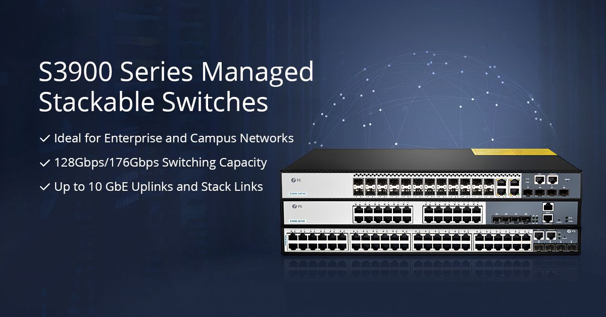
Recently, many people have jumped on the bandwagon to use the 24-port Gigabit managed switch with advanced administrative controls. In particular, 24-port switch with PoE technology provides people with great convenience. However, the more power it sustains, the noisier it is. Have you been hassled by the endless noise or interrupted in your work? It is time to put an end to work frustration with fanless 24-port Gigabit switch.What’s the Magic with Fanless 24-Port Gigabit Switch?A Gigabit Ethernet switch without fan doesn’t mean that it does not have cooling system. Instead, it adopts a passive cooling system which achieves high level of natural convection and heat dissipation by a heat spreader or a heat sink to maximize the radiation and convection heat transfer modes. The passive cooling makes your switch dumb but not numb, as it still works efficiently. In a word, fanless switch is the most suitable in silent and energy-saving environments. Here introduce three distinctive fanless 24-port Gigabit switches.Fanless 24-Port Gigabit Switch RecommendationFS 2800-24T4S Fanless 24-Port Gigabit SwitchS2800-24T4F 1000Base-T switch features 24-port 100/1000Base-T ports and 4 combo RJ45 SFP ports that enable user to mix fiber and copper cabling on a single switch. This 24-port Gigabit fanless switch is designed to meet the demand of cost-effective Gigabit access or aggregation for enterprise networks and operators. It adopts high performance processor to provide full speed forwarding and line-dormant capacity to offer customs multitudinous service features. In addition, S2800-24T4F supports multiple configuration modes to make it easy for network management and maintenance. This switch comes with a four-year limited warranty, including any quality problems during the free maintenance.HP ProCurve 1800-24G Fanless 24-Port Gigabit SwitchThe ProCurve Switch 1800-24G is a 22-port 10/100/1000 switch with 2 dual-personality ports for RJ-45 10/100/1000BASE-T or mini-GBIC fiber Gigabit connectivity. This fanless switch is managed via an intuitive Web interface, ideal for deployment in open offices or homes that require silent operation. It can be mounted on a desk, shelf, wall or in a rack cabinet. However, the demerit of this 24-port gigabit switch is that it doesn’t possesses stacking port.FS 3900-24T4S Fanless 24-Port Gigabit SwitchFS newly-released S3900-24T4S 10/100/1000BASE-T 24 port Gigabit switch comes with 4 10GE SFP+ uplinks ports. Since its debut, it has gained a lot of attention by its multifunction. As an advanced layer 2 Plus (layer 3 Lite) Gigabit managed switch, it supports stacking with 10G uplinks. In addition, the S3900 24-port gigabit stackable switch offered by FS boats an user-friendly web interface which makes it a snap to configure ports. An industry-standard command-line interface (CLI), accessed through the console port or Telnet, helps simplify the setup and operation of the network. The S3900-24T4S 24-port managed switch is almost an omnipotent switch for choice under many circumstances.ConclusionKill the noise, and attend to your work. Fanless 24-port Gigabit switch ensures noiseless operation and increases the reliability and energy efficiency of the system. Listening to the voice of customers to understand customer issues, FS, a network solution provider, strives to provide innovative and professional solutions for you.Related Articles: Should You Buy a Fanless Switch or Switch with Fan? FS 24 Port Gigabit Switch Selection Guide
2018.11.10
コメント(0)
-
24-Port Switch Price and Performance Comparison
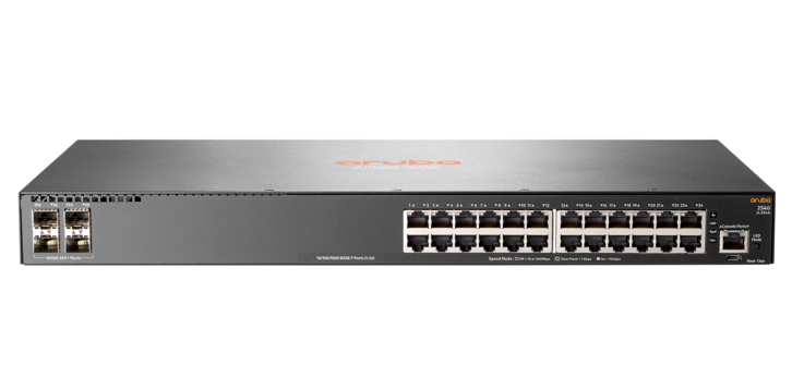
24-port Ethernet switch not only adds more ports for your home router, but also becomes a preferable option for enterprise networks, with dramatically decreased price, expanded feature sets and improved ease of use. Most 24 port switch price are acceptable for users. Here we introduce four 24-port Gigabit switch and make a 24-port switch price and performance comparison.24-Port Switches IntroductionAruba JL354A 24-Port Gigabit SwitchAruba JL354A is a 24-port layer 2 managed Gigabit switch. It is equipped with 24 10/100/1000 Gigabit RJ45 ports and 4 SFP+ ports. It supports advanced security and network management tools like Aruba ClearPass Policy Manager and Aruba AirWave, facilitating the deployment and management. The Aruba 24-port layer 2 managed Gigabit switch delivers entry level features for the enterprise campus, SMB and branch offices. It provides built-in 10GbE uplinks, robust QoS, static and RIP routing, IPv6, and requires no software licensing.FS S3900-24T4S 24-Port Gigabit SwitchFS newly-released S3900-24T4S 10/100/1000BASE-T 24 port Gigabit switch comes with 4 10GE SFP+ uplinks. It is an advanced Layer 2 Plus (Layer 3 Lite) Gigabit managed stackable switch with 10G uplinks. This Gigabit switch is perfect for service providers (ISPs) and multiple system operators (MSOs) to provide home users with triple-play services. Compared with the previous S3800-24T4S stackable switch, S3900-24T4S uses the 24-port switch fanless design, leaving you a comfortable peaceful environment. In addition, the S3900 series switches offered by FS boast nicer web interface which makes it a snap to monitor switch performance, configure ports, even set up port trunks, VLANs, and traffic prioritization. When configuring VLAN, they just require one command and an additional reboot step.Netgear ProSAFE GS724T 24-Port Gigabit SwitchThe Netgear ProSafe GS724T is armed with 24 copper 10/100/1000 ports, each capable of powering 2000 Mbps of data throughput in full-duplex mode per port, as well as 2 SFP 100/1000 ports. This 24-port switch enables SMB organizations to harness applications like VoIP, video conferencing, and system security, etc. And it features a fanless system, allowing the switch to work silently without overheating.TP-Link TL-SG1024 24-Port Gigabit SwitchThe TP-Link TL-SG1024 features 24 Gigabit Ethernet ports and non-blocking switching. It can realize large file transferring and also support 10Mbps and 100Mbps Ethernet devices. Moreover, this network switch has 48Gbps switching capacity with 8K MAC address table, 10KB Jumbo Frame and 4MB buffer memory. This TP-Link switch is a fanless rack mount design with LED diagnostic lights indicating the working condition of each port.24-Port Switch Price and Performance ComparisonGigabit SwitchesEthernet PortsSFP+ Uplink PortsSwitching CapacityForwarding RatePower ConsumptionPriceAruba JL354A244128Gbps95.2Mpps29.3 W$692.00FS S3900-24T4S244128Gbps95Mpps21 W$279.00Netgear ProSAFE GS724T24/48GbpsNot Sure29W$299.99TP-Link TL-SG102424/48Gbps35.7Mpps13.1 W$79.99In the above chart, four 24-port Gigabit switches are compared in Ethernet pots, SFP+ uplink ports, switching capacity, forwarding rate, power consumption and price which are mostly concerned by customers. All the Gigabit switches listed provide 24 port Ethernet RJ45 ports, but only FS S3900-24T4S and Aruba JL354A 24-port Gigabit switch have 4 SFP+ uplink ports. In addition, FS S3900-24T4S 24-port Gigabit switch is stackable. If you need stronger data transferring capability, FS S3900-24T4S is a better choice considering its competitive forwarding rate. In terms of the power consumption, TP-Link TL-SG1024 and FS S3900-24T4S are lower than others. With regard to 24-port switch price, TP-Link TL-SG1024 is the best budget choice. However, FS S3900-24T4S is cost-effective as it not only provides 4 SFP+ ports to create up to 10 Gbps high-speed uplinks and stack links to enterprise or campus networks but also works smoothly without generating noise.ConclusionTo sum up, the four Gigabit switches all have their own advantages. What’s more, 24-port switch price is moderate enough and with a few additional researches you will find that 24-port switch price is much lower than that of a 48-port switch whose ports may be idled in some conditions, causing unnecessary waste. There are also many other brand switches in the market, like 24-port switch Cisco SGE2000 and 24-port switch D-link DGS-1024D which enjoys a good reputation. The S3900-24T4S 24-port gigabit stackable switch provides small and medium-sized enterprises with a network that is geared for growth while ensuring performance and reliability.
2018.11.02
コメント(0)
-

Necessary Tips for Fiber Optic Cable Installation
FTTH, the concept that has been hotly debated by people in recent years, drives the demand for fiber optic cables and its related products. However, fiber optic cable is fragile and hard to splice, which is worthy of consideration before installation. To make good use of fiber optic cable, well-organized fiber optic cable installation is a necessity.Fiber Optic Cable IntroductionFiber optic cable is a technology that uses small threads made of glass or plastic (fibers) to transmit data. However cheap and light it is, the material brings a troubling problem in fiber optic cable installation. It is an assembly similar to an electrical cable while the former one carries light and the latter carries electricity. Normally, fiber optic cable comes in two types, namely, single mode fiber (SMF) and multimode fiber (MMF). Single mode fiber is suitable for long distance data transmission while multimode optical fiber is used in short distance transmission such as computer network linking. Regardless of fiber optic cable types you use, it is necessary to maintain a good fiber optic cable installation.Benefits for Good Fiber Optic Cable InstallationGood Working PerformanceGood fiber cable installation ensures the highly effective and smooth working of the fiber optic cables. The cables can not only conduct high-speed signal transmission, but also carry more bandwidth. Moreover, if operate inside a large building or fiber optic home wiring, the signal will be strong everywhere in each room, for the fiber optic cables can carry strong signal strength over long distances.Less Maintenance and RepairsThere’s nothing more annoying than a frequently breaking down cable system. A good fiber optic cable installation can spare you a lot of energy in the future maintenance and repairs, preventing endless frustrations. As for making a good structural installation plan, there are many things to consider. The next part will shed light on fiber optic cable installation guidelines.Guidelines for Fiber Optic Cable InstallationFiber cable installation can be categorized into different types, namely aerial fiber installation, direct burial installation, underground duct installation and household fiber cable installation. Regardless of the cabling condition, bear in mind the following guidelines.Start with proper planning so as to avoid mistakes and problems. Inspect the route before cable installation, detect the possible problems and get the solutions. Decide the number of cabling and connections needed. Moreover, we’d better consider planning ahead for installing additional cabinets, servers and network components.Test every fiber optic cable before and after the installation. For, example, use visual fault locator to find breaks in fiber cable. Make timely replacement or repairs to guarantee the normal installation process.Do not bend or kink fiber cables. Never exceed the cable bend radius of the fiber patch cord. These will harm the fibers. Use necessary tools to maintain a minimum bend radius of the installed fiber optic cable. Another way is to use bend insensitive fiber cables. Some vendors like FS provides BIF fiber patch cord of 10mm maximum bend radius, which is more flexible in cabling.Do not mix or match varied core sizes. Here recommends cable ties to bind the same type of cables together in case of confusion. Cable labels also can be used to mark different cables for easy identification.Use proper tools and techniques. Tools such as fiber patch panel, cable management panel can keep a well-organized cabling. And fiber enclosures can protect cables from external damage and are dust-proof. Fiber raceway can be installed overhead to route and support the cables. FS highly trained and skilled experts specialized in data cabling installation and fiber optic cabling installation are equipped with the necessary tools to create both permanent and temporary joints between fibers according to fiber optic cable installation standards.ConclusionIt is undeniable that fiber optic cable is worthwhile trying. However, do not follow suit to buy what you actually don’t need. Make clear of its advantage and figure out the fiber optic cable installation. First and foremost, read through this article.Related Articles:What Is Fiber Optic Cable and How Does It Work?Bend Radius—How It Can Impact Your Cable Performance?
2018.10.18
コメント(0)
-

How to Configure DHCP for Multiple VLANs?
Almost every device connected to the Internet needs an IP address. Previously, the countless IP addresses are assigned manually, which costs a lot of time and energy. As DHCP emerges, IT specialists are not required any longer to spend countless hours providing IPs for every device connected to the network device. But what is DHCP? How does it work and how to configure DHCP for multiple VLANs?What Is DHCP?DHCP – Dynamic Host Configuration Protocol is a network management protocol used on TCP/IP network. There may be at least a DHCP server and many DHCP clients. The DHCP server allows the client to request the IP addresses and other network configurations from the Internet service provider. This process eliminates the need for administrators or users to assign IP address to network devices one by one. Using this protocol, the network administrators will just set up the DHCP server with all the additional network information, and it will do its work dynamically. Both network switch and router can be configured as a DHCP server.How Does the DHCP Process Look Like?For the DHCP client that hasn’t accessed the Internet before, it will undergo 4 phases to connect the DHCP server.Fig 1. DHCP process1.DiscoverDHCP client after being activated will first send a broadcast message to try to look for DHCP servers. In this way, the client request IP address from the DHCP server.2.OfferWhen the DHCP server gets the message from the client, it looks in its pool to find an IP address it can lease out to the client. It then adds the MAC address information of the client and the IP address it will lease out to the ARP table. When this is done, the server sends this information to the client as a DHCPOFFER message.3.SelectionDHCP client chooses IP address. There may be several DHCP servers sending DHCP-Offer packet, the client only receives the first DHCP-Offer then sends back DHCP-Request packet in broadcast mode to all DHCP servers to request more information on the IP address lease time and verification. The packet includes the contents of the IP address requested from the selected DHCP server.4.AcknowledgeWhen the DHCP server receives a DHCP-Request packet from the DHCP client, it confirms the lease and creates a new ARP mapping with the IP address it assigned to the client and the client’s MAC address. And then send this message as a unicast to the client as a DHCPACK.How to Configure DHCP for Multiple VLANs?The theory cannot be well digested unless it is combined with the practice. In this section, how to configure DHCP for multiple VLANs is introduced for your reference. Take the following picture as an example.Fig 2. DHCP Configuration for Multiple VLANsPC1 and PC2 are connected to access port of VLAN switch 1 with VLAN ID 100 and 200.The DHCP server was supposed to serve both the VLANs.Command to enable multiple VLANs.Command to enable DHCP.Add both subnets.Run DHCP server.Now make PC1 and PC2 as DHCP client. Both should be able to get IP address from DHCP server in their respective VLAN.ConclusionHow to configure DHCP for multiple VLANs? This issue has been illustrated in the above content. DHCP configuration is worthy of being learned by those who are engaged in fiber optic communication field. You just need to know “How”, and let FS provide you with the best network devices. Ethernet switch like gigabit Ethernet switch and 10gbe switch, and routers are available in FS.
2018.10.10
コメント(0)
-

How to Use an Ethernet Switch?
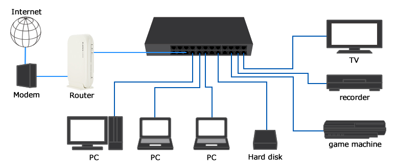
For many household use, it is common to see just a modem and a router. That’s enough for most family network requirements. However, if you have too many computers to manage, an Ethernet switch is definitely what you need. Since network switch is not prevalent in ordinary homes, many people don’t have a clear understanding of it, let alone its usage. Here we will figure out what is an Ethernet switch used for and how to use and Ethernet switch.What Is an Ethernet Switch?An Ethernet switch is a network device used to connect different PCs, servers, laptops or other Ethernet devices to a local area network. In this way, the connected devices can communicate with each other. The switch utilizes an MAC access table to exchange data packets among these devices.Network switches come in many types. Different switches have different applications and functions. They may come in 16, 32 or 64 ports, and also in various port speeds. The basic speed is 10 megabit per second, then 100 megabit. And today we also have faster gigabit Ethernet switch which realizes 1000 megabits per second. Switches that contain more ports or higher speeds are suitable for more demanding conditions.What Is an Ethernet Switch Used for?The Ethernet switch plays an integral role in most modern Ethernet local area networks (LANs). Here introduces two switch types for different utilities. The one is the fool-proof unmanaged Ethernet switch and the other is the intelligent managed switch.Unmanaged Ethernet Switch for Small Size EnvironmentUnmanaged switches simply allow Ethernet devices to communicate with one another by providing a connection to the network. Unmanaged switches are truly plug and play devices. However, this simplicity of unmanaged Ethernet switches also limits the functionality of a network. Therefore, unmanaged switches are usually used for small size environments like home where the applications are relatively few and simplified.Managed Ethernet Switch for Data CenterManaged switch is more advanced than unmanaged switch as it not only possesses what the latter features with, but also can be configured and properly managed to offer a more tailored experience. Most managed switches are 10gbe Ethernet switch, 40gbe, 100gbe or much faster switches. Those can be deployed in large data center, server rooms and so on.How to Use an Ethernet Switch?Whether it is the unmanaged switch or managed switch, the usage remains essentially the same. It should initially access the network and the power supply. This part introduces using an Ethernet switch.First, connect modem to Ethernet input line. Modem is the device that brings the signal into the network.Second, connect router to modem. Router translates the private network address into public address so as to entitle all the connected network devices to the Internet.Third, connect an Ethernet cable to one port on the switch, then connect the other end to a wired device such as a computer. Repeat this step to connect all PCs, servers, laptops or other Ethernet devices.Fourth, connect an Ethernet cable to one of the ports at the back of the switch, then connect the other end of the cable to one of the Ethernet ports at the back of the router. The switch is thus becoming the extension of the router. You plug in one output to your router, and the other ones will just split up that connection to give you more hookups.Fifth, connect the supplied power adapter to the power port on the switch, then connect the other end into a power socket. This step can be omitted if it is a PoE switch.Fig 1. Ethernet switch setup diagramHaving finished the connection, the unmanaged switch is ready to go while the managed switch may require further adjustments through a supported method, whether it is a command line interface (accessed via secure shell, etc.), a web interface loaded in your web browser or Simple Network Management Protocol (SNMP) for remote access. This approach will unleash various options, including port speed, virtual LANs, redundancy, port mirroring, and Quality of Service (QoS) for traffic prioritization.ConclusionThis article introduces Ethernet switch and illustrates how to use an it. Ethernet switch is basically regarded as the port extension of the router, and also grows with more functions as the network expands. As for the issue—how to use an Ethernet switch with router, please read the post “Network Switch Before or After Router”.
2018.10.06
コメント(0)
-

What Does a Network Switch Do in Networking?
As network switch evolves, there emerge various switches from different vendors, working in conditions, equipped with different functions. However, the network switches remain essentially the same despite all apparent changes. So, the following part presents the switches definition and the frequently asked question: what does a network switch do.Purpose and Functions of a Network SwitchA network switch is a small hardware device that centralizes communications among various linked devices in one local area network (LAN). The fundamental function of a network switch is to exchange data packages among network devices, that is to say, the network switch gets data from any source associated with it and dispatches that data to the appropriate destination. Here take the comparison among router, hub and switch to explain what a network switch can do for our networks.Providing More Ethernet PortsAs for network switch vs. router, network switch differs from router in the port number. Home routers usually come with three or four Ethernet ports built-in, and there are few free ports after connecting the router with the modem. So the Ethernet switch can work as the extension of router ports. In this way, it is possible to use wires to improve your speed or cut down on wireless interference.Enabling More Intelligent Data TransmissionNetwork switch sends data packets to the specific one or more devices, while a hub gets the information and forwards that to every other device apart from the one that really needs the information. To develop a step further, the network switch uses full duplex mode, and communication between different pairs may get overlapped but not interrupted. Whereas in hubs, all devices have to share the same bandwidth by running in half duplex mode, causing a collision, which results in unnecessary packet retransmissions.As for network switch vs. hub, a network switch joins multiple computers together within one local area network (LAN). A hub connects multiple Ethernet devices together, making them act as a single segment.Three Main Types of Network SwitchTo make full use of your network switch, the priority is to make clear of its function as different switches come with different capabilities. There are three types of switches in networking: managed switch, unmanaged switch, and smart or hybrid switch.Managed SwitchManaged switch offers full management capabilities and high-levels of network security and precise control, and usually used in enterprise networks and data centers. The scalability of these switches entitles networks room to grow.Managed switches can optimize a network’s speed and resource utilization. Admins manage resources through a text-based command-line interface, so some advanced knowledge is required to set up and run. Most managed switches are 10gb Ethernet switch, 40gb Ethernet switch and 100gb switch.Unmanaged SwitchFor unmanaged switch, the gigabit Ethernet switch itself has no settings or special features, and it exists only to add more Ethernet ports to your home network or small business offices or shops. Additionally, it is easy plug-and-play and relatively simple, so it’s great for companies without IT admins and senior technologists.Smart or Hybrid SwitchSmart switch is partly a managed switch, as it offers functions like Quality of Service (QoS) and VLANs, but with limited capabilities that can be accessed from the Internet. Its interface is simpler than what managed switch offers. Therefore, no highly-trained staff is needed to set up or run it. It is great for VoIP phones, small VLANs, and workgroups for places like labs. In a word, smart switches let you configure ports and set up virtual networks but don’t have the sophistication to allow monitoring, troubleshooting, or remote-accessing to manage network issues.ConclusionThe above content summarizes the issue: what does a network switch do. Based on that, three types of switches come with distinct functionality. FS offers a great range of network switches with different features. It has taken all your needs into consideration when producing and testing these switches.
2018.09.27
コメント(0)
-

Core Switch Vs Distribution Switch Vs Access Switch
The hierarchical internetworking model defined by Cisco includes core layer, distribution layer and access layer. Therefore, the network switches working in these layers get corresponding names like core switch, distribution switch and access switch. This post mainly explores the confusing problem: core switch vs distribution switch vs access switch.Definition: Core Switch Vs Distribution Switch Vs Access SwitchWhat Is Core Switch?Core switch is not a certain kind of network switch. It refers to the data switch that is positioned at the backbone or physical core of a network. Therefore, it must be a high-capacity switch so as to serve as the gateway to a wide area network (WAN) or the Internet. In a word, it provides the final aggregation point for the network and allows various aggregation modules to work together.What Is Distribution Switch?Similarly, the distribution switch lies in distribution layer, and it links upwards to layer core switch and downwards to the access switch. It is also called aggregation switch which functions as a bridge between core layer switch and access layer switch. In addition, distribution switch ensures that the packets are appropriately routed between subnets and VLANs in enterprise network. 10gb switch usually can perform as a distribution switch.What Is Access Switch?Access switch generally locates at the access layer for connecting the majority of devices to the network, therefore it usually has high-density ports. It is the most commonly-used gigabit Ethernet switch which communicates directly with the public Internet, mostly used in offices, small server rooms, and media production centers. Both managed and unmanaged switches can be deployed as access layer switch.Figure 1: core switch vs distribution switch vs access switchComparison: Core Switch Vs Distribution Switch Vs Access SwitchThe switches may co-exist in the same network, and coordinate with each other to contribute to an unrestricted network speed with each layer switch performing its own duty. Well, what’s the difference: core switch vs distribution switch vs access switch?Core Switch Vs Distribution SwitchCore switch has the higher reliability, functionality and throughput than distribution switch. The former one aims at routing and forwarding, and provides optimized and reliable backbone transmission structure, while the latter one functions as the unified exit for access node, and may also do routing and forwarding. The distribution switch must has large enough capacity to process all traffic from the access devices. What’s more, there’s generally only one (or two for redundancy) core switch used in a small and midsize network, but multiple distribution switches in distribution or aggregation layer.Core Switch Vs Access SwitchThe lower levels the switch dwells in, the more devices it connects to. Therefore, a big gap of ports number exists in access switch and core switch. Most access switches need to connect various end user equipment ranging from IP phone, to PCs, cameras etc,. While the core switch may be just linked with several distribution switches. Meanwhile, the higher layer the switch lies in, the faster port speed it requires. Access switch is to core switch what river is to the ocean, as the latter one has the large throughput to receive the data packets from the former one. Most modern access switches come with a 10/100/1000Mbps copper ports. An example of this is FS S2800-24T4F 24 port 100/1000BASE-T copper gigabit Ethernet switch. While core switches commonly have 10Gbps and 100Gbps fiber optic ports.Distribution Switch Vs Access SwitchAs access switch is the one that allows your devices to connect the network, it undoubtedly supports port security, VLANs, Fast Ethernet/Gigabit Ethernet and etc. Distribution switch which is mainly responsible for routing and policy-based network connectivity supports additional higher performance like packet filtering, QoS, and application gateways. All in all, access switch is usually a layer 2 switch and distribution switch is a layer 3 switch. When multiple access switches among different VLANs are required to be aggregated, a distribution switch can achieve inter-VLAN communication.ConclusionWhat’s the difference: core switch vs distribution switch vs access switch. To sum up, the access switch facilitates devices to the network. The distribution switch accepts traffic from all the access layer switches and supports more high-end features. And the core switch is responsible for routing and forwarding at the highest level. FS provides different types of Ethernet switches that can work as core switches, distribution switch or access switches. For more details, please visit www.fs.com.
2018.09.20
コメント(0)
-

Get Further Understanding of Ethernet Switch Port Types
Have you ever noticed the ports on your gigabit PoE switch or other network switches? They may come in different port types and work on different switch port modes. The switch ports number varies from different network switches and port type can be configured according to specific needs. Then how many ports on a switch? What are the common switch port types?How Many Ports Does a Network Switch Have?Generally, I’d like to assort the ports on the switch into the ones that enable others to work and the ones to realize its own operation. The former may be classified into different types of ports based on their port speeds as shown in the following diagram, and the latter is referred to the console port. Almost every switch has a console port used to connect to the computer and manage the switch as the switch has no display component.Here takes FS gigabit switch, 10GB Ethernet switch and 40G/100G Ethernet switches as examples to show the switch port types and numbers that a network switch may have.S3800-24T4S1GB Ethernet SwitchS5800-8TF12S10GB Ethernet SwitchS5850-48T4Q40GB Ethernet SwitchS5850-48S2Q4C100GB Ethernet SwitchRJ45 port8848/SFP port88/48SFP+ port1212//QSFP+ port//42QSFP28 port///4As the above figure shows, a network switch may support diversified ports. The common port number of FS network switch is 8, 24 and 48. While the maximum number of ports in a switch can grow as demands.Common Switch Port Types on Network SwitchesWhen the data switch resides in a VLAN, there may be three common switch port types: access port, trunk port and hybrid port. An Ethernet interface can function as a trunk port, an access port or a hybrid port.Switch Port Types: Access PortAccess port is used for connecting devices such as desktops, laptops, printers etc., only available in access link. A switch port in access modes belongs to one specific VLAN and sends and receives regular Ethernet frames in untagged form. Usually, an access port can only be member of one VLAN, namely the access VLAN, and it discards all frames that are not classified to the access VLAN.Switch Port Types: Trunk PortTrunk port is adopted among switches or between switch and upper-level devices, available in trunk link. A trunk port allows for several VLANs set up on the interface. As a result, it is able to carry traffic for numerous VLANs at the same time. Frames are marked with unique identifying tags—either 802.1Q tags or Interswitch Link (ISL) tags—when they move between switches through trunk ports. Therefore, every single frame can be directed to its designated VLAN. The trunk port is a VLAN aggregation port connected to other switch ports while the access port is the port that the switch connects to the host in the VLAN. The following picture shows their differences.Switch Port Types: Hybrid PortHybrid ports can be used to connect network devices, as well as user devices. It supports both untagged VLAN like access port and tagged VLAN like trunk port, and it can receive data from one or more VLANs. The hybrid ports resemble trunk ports in many ways, but they have additional port configuration features. Hybrid port can send some packets without tag to PC or IP phone, and others packets with tag to other device which can process tag.ConclusionKnowing the switch ports number can help you select the right switch for you. And figuring out the switch port types helps you configure your switch ports accordingly. This post introduces the three basic switch port types and their differences. Hope it will be helpful for you.
2018.09.13
コメント(0)
-
Network Switch Before or After Router?
Network switch and router are the commonly used devices in a network. With each carrying out its own duties accordingly, you can surf on the internet freely with your smart phone or computer. How to setup a network switch and router? Should the network switch be installed before router or after router is puzzling for many network newbies.What Is Network Switch and Router?To get clear about how to connect wireless router to switch, this part will state the function of network switch and router first. What is a switch in networking? A network switch is used to connect multiple devices such as computers, printers, IP camera and modem on the same network within a building. In this way, these devices can share information and communicate with each other.What is a router in networking? A router is sometimes connected to a modem at one side and many other devices on the other side. Because the modem will only talk to the first computer that talks to it, the router at the position serves like a dispatcher to share the connection among all your devices. This enables all connected computers to share one single Internet connection.Fig1. Home network diagram with switch and routerHow to Setup a Network Switch and Router?From the above introduction, we know that both the network switch and the router can be connected directly to a modem. However, when the two devices coexist, how to deploy them. Shall I connect modem to router to switch or modem to switch to router?Modem to Router to Switch: Network Switch After RouterIn most cases, you will see people put the modem first, followed by a router and then a gigabit Ethernet switch. The principle is that the modem gives the public IP address to the router, and the router assigns the private addresses to the devices connected to it, while the network switch doesn’t handle allocating IP addresses but serves as the extension of the limited ports on the router, to receive more devices. In this scenario, all your devices with private addresses are safe as they are not directly visible to the internet.Fig2. Modem router switch diagramModem to Switch to Router: Network Switch Before RouterSome people propose going from a cable modem to switch to wireless router. This seems good because all your devices on the network switch will have direct connections to your ISP. However, the truth is, your ISP does not offer multiple public IP addresses before the full transition from IPv4 to IPv6. So one or all ISP connections will likely fail and all of the devices connected to the switch would be exposed to the internet.In a word, placing a modem to switch to router is not possible. At least not practically. Each port on the switch is a different IP address. So it doesn’t exist? Probably not unless your modem integrates the function of a router so that you can rewire and reconfigure the wireless router to set it up as access point. Seen from the outside, you indeed put a managed switch before router, however it still follows the principle that router goes before network switch.ConclusionNetwork switch before router or after router? Have you made it clear? This post has stated modem to router to switch vs modem to switch to router. Hope when you set up your network with router and switch, you can put them in the correct order according to your needs and the products themselves (the modem type). Here at FS.COM you can find various network switches including 10 gigabit switch, 40 gigabit switch and 100 gigabit switch, etc.
2018.09.04
コメント(0)
-

What Is ACL (Access Control List) and How to Configure It?
Though the robust network promotes the connectivity among people at every comer of the globe, we may not enjoy its convenience or gain the information we want as easily and casually as it thought to be. Due to the access control list, some paths to a certain server may have been blocked manually. Well, what is access control list? Why does it get in my way to the fantastic world?What Is ACL (Access Control List)?ACL stands for Access Control List. It is a list of a series of rules that are specified to permit or deny traffic flow. More precisely, ACL serves to filter data packet based on a given filtering criteria on a router or data switch interface, thereby controlling access to your network or to specific files or folders on your network. How does ACL work? As we all know, when a router receives a packet, it will routinely identify its destination address and find an entry in routing table that can match with it. If succeed, the packet can be forwarded, otherwise, discarded. We can run ACL conditions before or after the router makes forward decision. If deny condition matches, drop the packet immediately, otherwise, move on to the next step as normal.There are mainly two types of ACL, namely standard ACL and extended ACL. The former one only specifies the source address while the latter can permit or deny traffic based on both the source and destination addresses as well as the ports (for TCP or UDP), or the IPCMP type (for ICMP).Why Do We Need Access Control List?First, it works as a security for your network by filtering the unwanted traffic and blocking specific hosts. In the above scenario, if we exclude the ACL, anyone who knows the right destination address can send his packet through the router with no security policy, and damage may ensue. Given this, you can customize ACL conditions to decide who has access to resources in the network.Besides, ACLs are used for several other purposes such as prioritizing traffic for QoS (Quality of Services), triggering alert, restricting remote access, debugging and so on.How to Configure Access Control List?We’ve produced a video for your better understanding of ACL network and ACL configuration. FS S5800/S5850/S8050 series switches are used in this video. Here are the basic access control list commands.This step helps enter the global configuration modeIn this step, we create an ACL, and its number is “123”. Then we can add rules to the ACL. Please note that ACL number for the standard ACLs has to be between 1—99 and 1300—1999, and extended access list numbers ranges from 100 to 199, and from 2000 to 2699.Use the host keyword to specify the host you want to permit or deny. This means that deny tcp host 192.168.1.2 access to 192.168.1.1.The command above permits all message.Here create a class-map and name it “http”.Match the access control list of “123”.Create policy-map “web”.Associate the class-map “http” with the policy-map.Enter the eth-0-1 port on FS S5850-32S2Q 10gbe switch.Invoke the policy table “web” in the inbound direction of the interface.The series of operations ban successfully the address 192.168.1.1 from entering the switch now.ConclusionHaving read this article, you may get acquainted with access control list and know how to configure it. The ACL network helps prevent others from entering into your private network space while keeping you out from where others don’t let you in. Everyone can adopt it to manage your own networking condition. In this way, FS provides you with good quality equipment like fiber switch and PoE network switch and best solutions.
2018.08.28
コメント(0)
-

Server Rack Sizes: How to Choose a Right One?
A server rack is an equipment that holds all kinds of network devices ranging from switches, patch panel racks, to cable organizer and so on. Generally, the very first step in rack cable management is to get a container like 42U server rack to support all your devices. However, as there are so many server rack sizes on the market, how to get the one that is ideal for your application needs to be well thought of. Here we can offer some way out.Common Server Rack SizesBased on different application requirements, different server rack sizes are produced. The three common types of server racks are open frame rack, rack enclosure and wall-mount rack.Server Rack Sizes: Rack EnclosureThe rack enclosure, also known as server rack cabinet, usually comes in 40U,42U or 45U. It contains removable doors at both front and rear sides, removable side panels and adjustable vertical inside mounting rails, which provides an easy way to install and take out devices. The specially designed perforated door allows for smooth ventilation. Server rack cabinet may come in different height and depth. The height is usually represented by “U” and one U space equals to 1.75 inches. Whereas the depth refers to the distance between the front of the rack and the rear. FS.COM offers 9U server rack, 12U server rack, 42U server rack and 45U server rack. There may be server racks with 48u rack height on the market, which can accommodate as many as 24 2U devices.Server Rack Sizes: Open Frame RackOpen frame rack resembles rack enclosure in shape, but it is designed without doors or side panels. Just two or four bare rails are largely economical and leave easy access to cabling. And its common rack size is 45U. Ventilation is no longer a headache for expertise. However, it may expose all your applications to the external environment, resulting in bad appearance or even damage. Given this, open frame racks are optimal for network wiring closet and distribution frame applications that have high-density cabling.Server Rack Sizes: Wall-mount RackWall-mount rack, the relatively small server rack fixed on the wall, is like a miniature rack enclosure. Usually, the wall-mount server rack sizes are 6U, 9U, 12U and 18U. As it doesn’t occupy the floor space as the former two, the wall-mount cabinet is spacing-saving which can be its selling point. It is suitable for your household use which does not include large and complicated equipment.How to Choose from These Server Rack Sizes?If you are not restricted by the space, you can choose from the rack enclosure and open frame server rack. Just calculate the required height and depth of your applications. For example, assume that you need to add 5 2U rack servers to your data center. A 12U server cabinet(21 inches) would be ideal, because 2 x 1.75 x 5 = 17.5 inches of space. The same is to the depth. Remember leaving some cabinet space for both the front and rear for future expansion and current rack cable management. Otherwise, a wall mount server rack is recommended as it is space-saving when you don’t have enough room for floor-standing cabinet. Check out the maximum weight it can hold.ConclusionSince the server rack is not flexible or scalable, we must plan carefully for the server rack sizes, and take into consideration the dimension and shape of server racks. As for the quality, rest assured that FS.COM offers sturdy cabinets with reasonable price. We are ready to provide you with the best solution.Related article: Wall Mount vs Rack Mount Patch Panel
2018.08.22
コメント(1)
-
How to Use Vertical Cable Organizers for Rack Cable Management
Cable management, especially rack cable management, is a always the time-consuming and tedious job for IT network workers. Cable organizers like patch panel, 1U/2U cable managers and D-rings are commonly used by network workers in server rack cable management. Then how to use these cable organizers for rack cable management effectively? This article will explore some details for you.Single-sided Cable Organizer in Rack Cable ManagementThe single-sided vertical cable organizers, also known as cable manager, are usually installed on open frame racks to organize and protect cables. As it is single-sided, the finger ducts are facing towards the front side or users. It is in most cases attached to the rack and won’t take up much room in rack cable management. The 45U single-sided cable organizer provided by FS.COM is capable of managing all the fiber and copper cables in a server rack. It is equipped with molded cable management fingers which have integral bend radius control. Each of this single-sided vertical cable manager consists of two 22.5U sections in one package. The two parts can be seamlessly combined together when they are installed along a standard 45U height server rack. The user-friendly cover on this rack cable organizer can help protect the cable from damage and dust-proof, and also hide the cables inside.Dual-sided Cable Organizer in Rack Cable ManagementDifferent from the single-sided cable organizer, the dual-sided cable manager is designed with management fingers on both front and rear sides. The double-sided structure enables the maximize space utilization, which can better meet the vertical cable management need. The 45U plastic dual-sided vertical cable organizer is deployed to deal with the slack cables, preventing the chaotic cable runs. Its soft finger ducts on front and back sides allowing for quick and easy cable routing on the server racks. Two 22.5U sections being coupled seamlessly form a complete 45U dual-sided vertical cable manager which is suitable for both fiber and copper cabling. The covers on both sides can protect cables from damage and dust. It can be a good partner of horizontal cable managers. In addition, this vertical cable manager has multiple finger ducts that can store a large number of cables.How to Use Vertical Cable Organizers for Server RacksThe vertical cable organizers are often deployed where cables run chaotically. When applying them, assemble all the gadgets including the cover and the easily inserted brackets. Use screws to fix them on the open frame rack. After the two 22.5U dual-sided cable organizers being matched seamlessly, the cable management can go on. To produce a tidy and clean appearance, care should be given that the cables on the same row should be passed through the same gaps between two fingers. Get some cable ties to achieve better effects. After the cabling, close the cover. Success. Here is a video introducing how to apply vertical cable organizers in rack cable management.ConclusionVertical cable organizer, or vertical cable manager, can simplify rack cable management effectively. It has nothing to do with the network but serves the cable management. In the cabling system, only combing the cable runs clearly can the network system work in an orderly way. FS.COM has been all along working on the growing conundrum to offer you market-leading quality and novel design. We now have different cable organizers available for your reference to deal with vertical and horizontal cable management.
2018.08.17
コメント(0)
-

What Is Open Frame Rack and How to Use It?
There are many different types of server racks on the market, like open frame rack, server cabinet, and rack mount and wall mount enclosures. Open frame rack, thanks to its reasonable price, and material saving, has attracted more and more customers. It is more convenient to ship and be packed. To help you better understand the open frame rack, this article will introduce it in three aspects.Brief Introduction of Open Frame RackThe open frame rack is an equipment to mount your servers and other network equipment. When you deploy equipment and organize cables in a computer room or data center,it is important to make proper and reasonable space utilization. Therefore, open frame server racks come at a right time to help stay organized in a cost-effective manner. Here I list four benefits of open frame server racks and why you should consider them for you equipment storage needs.Benefits of Open Frame RackBetter Cable ManagementThe fact that you may run the cables with obstacles from doors and panels won’t frustrate you when using an open frame rack. It is just formed by 2-post racks or 4-post racks with no limitations to each orientation. With this rack, you will not consider whether it can contain all your applications within the space any more.AirflowThe enclosed racks are not easy for ventilation. Open frame server racks, on the other hand, allow for unrestricted airflow, preventing heat build-up. The proper cooling is conducive to the running of the whole system.Easy AccessWithout barriers, you can access to every equipment and route cables freely in every direction you want. And all the organs and working status are visible to you for real-time monitoring.CostOpen frame server racks are a cost-effective way to manage equipment, compared to enclosed racks. For example, the 45U 4 post open frame server rack sells at $300 and 2 post one $210, much cheaper than the 45U server cabinet selling at $650. The cost of producing and shipping is less than those of closed cabinet or server racks.How to Use Open Frame Rack?Take the FS.COM 45U 2 post open frame rack as an example, there are many mounting holes on the two posts on which you can attach different devices like cable organizer and patch panel rack in 19’’ standard. You’d better put it on the flat ground lest it fall down.The bold innovation, server rack without doors and panels, has been warmly welcomed by customers. Apart from the open frame rack, FS.COM offers a variety of racks and enclosures to meet your different applications and conditions. We aim to provide you with high quality products with reasonable price and best service. And we will forge ahead to deliver more versatile products to optimize your experience. If you are interested, follow us. We will release latest news of our achievements on products.
2018.07.21
コメント(0)
-

How to Choose a 48 Port Patch Panel?
Patch panel, the critical component in the data center, comes in various types. The port density of a patch panel may not be your primary consideration, but it indeed matters as the ports directly affects the cable management needs either at present or in the future. The number of these ports vary from 12, 24, 48, 64, 72, 96 to 288 and even more. Actually there is no limit to the number of ports on a patch panel. In this article, I’d like to share a buying guide about 48 port patch panel.48 Port Patch Panel: Copper VS. FiberNo matter how many ports they have, patch panels can be deployed in fiber and copper cabling system to organize and distribute cables. The 48 port patch panel is no exception. There is no practical difference in performance as the role of patch panels is to direct signal traffic rather than send the signal. However, there is indeed a difference between the cables they will wire. Fiber patch panel is mainly used in fiber optic cable management, while copper patch panel is designed for both shielded and unshielded copper cables like Cat5e, Cat6, Cat6a, and Cat7.Copper 48 Port Patch Panel RecommendationAs for the copper patch panel, it is designed according to the copper cable types. Sometimes, Cat5e, Cat6 or other Ethernet cables need to be managed in a single panel. In this situation, the blank keystone patch panels can support mixed cabling with installation of different rj45 insert modules. The 48 ports blank keystone/multimedia patch panel, manufactured by FS.COM, is made of SPCC CRS material. It can accommodate all keystone jacks, including RJ45 Ethernet, HDMI audio/video, voice and USB applications. In addition, the high density 19in wide, 1U High, panel design will save valuable space in the rack. With it, you can customize your patch panel according to your specific application.Fiber 48 Port Patch Panel RecommendationWhen it comes to 48 port fiber patch panel, you can choose it based on your fiber core, single mode or multimode. 1U 19" high-density fiber patch panel(ID:69082) can accommodate up to 96 fibers with 48 ports on it. As a fiber patch panel, it supports the OM3/OM4 multimode fiber mode. Designed with LC duplex on both sides, it saves much cost as being fully loaded with fiber couplers. Specifically, FS.COM comes up with an innovative design and cable management. The 1U detachable horizontal cable management panel can protect and organize fiber optic cable in your network.Roughly the same with the former fiber patch panel, this one, 96 fibers, 48 ports LC 9/125 single mode adapters, 1U 19" high-density fiber patch panel, supports OS2 9/125μm single mode fiber. Designed with high quality steel adapter panel, it is suitable for 1U 19" frame rack mount or cabinet. It can meets the requirements in backbone-to-backbone and backbone-to-horizontal fiber cabling.The 48 port patch panels introduced above are all from FS.COM, the company which wins people’s favor by its reasonable price and high quality. This company has been pressing ahead with novel and versatile products and all kinds of cabling solutions.
2018.07.14
コメント(0)
-

2U Cable Manager—Assist of Cable Management
What Is the “U” in 2U Cable Manager?What’s the difference between 1U and 2U cable managers? The most distinguishable one in my mind, is the number lying in their name. The “U”, also known as “RU”, stands for rack unit that is a unit of measure defined as 44.50 millimeters (1.75 in) by EIA. It is most frequently used as a measurement of the overall height of 19-inch and 23-inch rack frames, as well as the height of equipment that mounts in these frames. With this standard, we don’t need to play with complicated numbers, instead, a simple addition can work. For example, a 12U cabinet can accommodate twelve 1U devices or six 2U devices or four 3U devices. And so on.Where and When to Use 2U Cable ManagerAs the data center grows, you may have many cables to handle, thus the point-to-point cabling is not workable any longer. To realize and maintain a neat and clean cabling, you may need such tools as patch panels, enclosures, and cable managers, among which the cable managers are the primary consideration when you want a good cabling.1U and 2U cable managers are the most common products for horizontal cable management at present. As people’s demands vary, 2U cable managers come in to being. The 2U cable manager allows for front-to-back and back-to-front cable runs. The finger ducts can be used for both upside and downside cable management. These products can be used above and below patch panel and network switch to organize and store cables.2U Cable Manager OptionsFS.COM offers a wide variety of 2U horizontal cable managers that range from cable manager with finger duct to cable manager with D-rings and cable manager with end rings manager.2U Cable Manager with Finger DuctThis 2U cable manager is made of plastic in black coat. It is designed with flexible fingers, rear pass-through holes and a removable cover. The cover will enclose the cables within the fixed space, leaving the clean and neat appearance. In this way, people won’t see the tangled or crossed cables in it. The finger ducts are soft and durable, which offer proper bend radius and flexible operation of cable management, keeping the structured cabling system unhurt and totally functional.2U Cable Manager with 5 D-ringsAs an open-frame cable manager, it is made of metal with five D-rings standing on the panel in a good order. Horizontal cable management panels with D Rings are built with steel for strength and durability. Easily route large amounts of cable through robust rings. The D-Rings organize patch cords and maintain a required bend radius. They are available in sizes of 1U and 2U.2U Cable Manager with End Rings ManagerIt is a metal open-frame cable manager with vertical four rings and two horizontal rings, providing better cord management. It is also compatible with most standard 19” enclosures and open frame server racks, mounting hardware included. The end-rings will somehow protect the cables in case of unnecessary bending.All these 2U cable managers have 1U versions. To meet your various requirements, we strive to keep improving, innovates unceasingly, making the FS.COM attentively the first-class enterprise.
2018.07.06
コメント(0)
-

Create Your Structured Cabling Solutions
Have troubles in vertical or horizontal cable management in your data center? Confused at the cables’ destinations and start points? With slack cables hanging here and there in server rack, blocking and pathway? Well, all these issues brought by point-to-point cabling will become the thing of the past as the structured cabling comes into being.What Is Structured Cabling?Before the 1990s, data and cabling system were proprietary which means they were vendor specified, each vendor had his own cabling system design and it was hard to have products from different vendors to work together. In the mid 1980s, the EIA was asked to develop a specification that would encourage structured standardized cabling. In 1991 the TIA published the first version of the commercial building telecommunications cabling standard, better known as TIA/EIA-568.In the United States, we follow TIA/EIA-568-C as the structured cabling standard. It covers subsystems of structured cabling, installation methods and practices, connector and pin assignments, media types and performance specifications for horizontal and backbone cabling, connecting hardware performance specifications, recommended topology and distances, and the definition of cable elements (horizontal cable, cross-connects, telecommunication outlets, etc.)How to Design Your Own Structured Cabling SolutionPresume that we have an empty building of four storeys, we need to design a structured cabling solution for different uses in it. One solution we must apply, also one of the subsystems of structured cabling, is horizontal cabling which can not be skipped in each floors. Horizontal cabling is the cabling that extends from horizontal cross-connect or main cross-connect to the work area and terminate in telecommunications outlets. Horizontal cabling includes the following: 1.Cable from the patch panel to the work area; 2.Telecommunications outlets; 3.Cable terminations ; 4.Cross-connections(where permitted); 5.A maximum of one transition point; 6.Cross-connects in telecommunications rooms or enclosures.Furthermore, to achieve the connection between different floors, we need the backbone cabling, also known as vertical cabling. We can adopt it to to connect entrance facilities, equipment rooms, and telecommunications rooms and enclosures. Backbone cabling consists of not only the cables that connect the telecommunications rooms, equipment rooms, and building entrances, but also the cross-connect cables, mechanical terminations, or patch cords used for backbone-to-backbone cross-connection.The work area is where the horizontal cable terminates and wall outlets also called the telecommunications outlet. In the work area, the users and the telecommunications equipment connect to the structured cabling infrastructure. The work area begins as a telecommunications area and includes components such patch cables, modular cords, fiber jumpers, station equipment such as computers, telephones, fax machines and so on.The telecommunications rooms and telecommunications enclosures are the location within the building where cabling components such as cross-connects and patch panels are located. These rooms are where the horizontal structured cabling starts from. The telecommunications room and enclosure may also contain networking equipment such as hubs, switches, routers, etc.The equipment rooms is a centralized space specified to house more sophisticated equipment than the entrance facility or the telecommunications rooms. Most often, telephone equipment or data networking such as routers, switches, and hubs are located there. Backbone cabling is specified to terminate in the equipment room.The entrance facility specifies the point in the building where cabling connects with outside world. All external cabling such as campus backbone, inter-building, and telecommunications provider should enter the building and terminate in a single point.Digital data is growing faster than any other commodity and its importance to businesses of all types cannot be underestimated. To learn how you can use structured cabling to better manage your data center, contact the experts at FS.COM.
2018.06.28
コメント(0)
-
Panduit Fiber Optic Enclosure and FS.COM Fiber Optic Enclosure
Not so long ago, fiber optic communication came into people’s life and provided us with great convenience. Its advantages could be found in such aspects as long transmission distance, large capacity and fast transmission speed. Therefore, the demand of fiber optic products like fiber optic transceiver, fiber optic patch panel and fiber optic enclosures has been soaring these years. But the products on the market are miscellaneous. Today, we will have a closer look at the two major fiber optic enclosure manufactures, namely Panduit and FS.COM. Panduit fiber optic enclosure and FS.COM fiber optic enclosure, which will you choose?Comparisons of Fiber Optic Enclosures in Panduit and FS.COMPanduit is a global manufacturer of physical infrastructure equipment that support power, communications, computing, control, and security systems. FS.COM (Fiberstore) is a leading global high performance end-to-end cabling and connectivity solutions provider which provides a complete portfolio of products and solutions.Focusing on three groups including rack mount fiber enclosure, wall mount fiber enclosure and enclosure accessory(fiber optic cassette for example) which are all applied in 1U cable managemet, I have summarized several critical items that are most concerned by customers in the following table.Rack Mount Fiber EnclosureItemsFS.COMPanduitProductsFHD-1UFCE Fiber EnclosureFRME1 EnclosureFiber Count≤96 Fibers≤36 FibersTypeRack MountableRack MountablePrice≈89$≈190$WarrantyLifetime6 MonthsWall Mount Fiber EnclosureItemsFS.COMPanduitProductsFHD-FWME2 Fiber Optic Wall Mount EnclosureFWME2 EnclosureFiber Count≤48 FibersUnknownTypeWall MountableWall MountablePrice≈60$≈116$WarrantyLifetime6 MonthsFiber Optic Cassette—Enclosure AccessoryItemsFS.COMPanduitProductsMTP-12 Ultra High Density MPO/MTP CassetteFC26N-12-10ASFiber Count12 Fibers12 FibersDimension(HxWxD)11.3x92x171.2mm35 x 89 x 125mmPrice≈72$≈293.4$Panduit Fiber Optic Enclosure or FS.COM Fiber Optic EnclosureSeen from the clear data and information about 2 pairs of fiber optic enclosures form FS.COM and Panduit, we can distinguish that there is a large gap between the product price and warranty. FS.COM provides lifetime warranty while Panduit only offers 6 months warranty. A Lifetime Warranty means that products enjoy a warranty within their own practical life. FS.COM warranty covers all defects in materials and workmanship for all products sold and manufactured by FS.COM. Items with defects in materials and workmanship will be repaired or refunded. The price, another significant factor that influence purchase, is greatly different from each manufactures. Fiber count of the roughly same products are also different, with FS.COM products outnumbering Panduit ones.And the enclosure accessories provided by FS.COM cater to various needs. They have different fiber counts, connector types, and adapter types, and minimum insertion and return loss.Price, fiber count and warranty, the top three considerations of purchasers when looking for the ideal products, have been analyzed in the type of table and text for your reference.ConclusionWhen it comes to the choice between Panduit fiber optic enclosure and FS.COM fiber optic enclosure, you should figure out your own requirements to determine which to buy. The renowned Panduit and FS.COM both have their own reasons for each progress and designing. At FS.COM, we offer lifetime warranty and limited warranty for different products varying on the materials, workmanship, usage rate, and the availability of the spare parts for each product. And the relatively reasonable price is also the reason why so many people choose FS.COM. As a company born and grew in China, FS.COM grows with and by people. And it returns people with high quality and best service.All above are some of my personal opinions and conclusions. The thinking and words just represent my own idea, if you find out any unreasonable, please forgive me and your ideas will be appreciated.
2018.06.25
コメント(0)
-

Come to the New Tool of Horizontal Cable Management
Horizontal Cable Management ReviewAs one of the important tools in horizontal cable management and the assist of fiber panel, the horizontal cable manager has been warmly welcomed by the public since its debut. The horizontal cable manager comes in varied types such as brush strip cable manager, finger duct cable manager. And the height of it may vary as the network system demands. The fantastic design horizontal cable manager with finger duct is what we will talk about today.Horizontal Cable Manager with Finger Duct OverviewThe FS.COM finger duct horizontal cable manager is designed with flexible fingers, rear pass-through holes and a removable cover. It can be mounted to standard 19 and server rack and cabinet providing well-organized cabling quickly and easily. 1U and 2U versions are both available at FS.COM. Unique hinge cover allows for easy cable moves,adds and changes to connections, saving time and money. The soft and durable finger ducts offer proper bend radius and flexible operation of cable management. 2U version increases more space for Ethernet cable runs.The two holes on the main plate allow for front-to-back or back-to-front cable runs. The finger ducts can be used for both upside and downside cable management. Simplify network maintenance and cost, as well as support future growth and cabling demands.How the Finger Duct Horizontal Cable Manager Works?Take 1U finger duct horizontal cable manager as an example, it can be mounted above or below the fiber optic patch panel, with the hinge cover side facing towards us. Open the cover and 12 gaps between 11 finger ducts. The cable is inserted into the above patch panel, and then 2 cables share a same gap. The left 6 couples of cables are all combed to the left vertical cable manager, and the right 6 to the right horizontal cable manager. The two holes on the back of the cable manager are designed for the cables inserted to the below patch panel. The procedure is all the same with the front cabling.With all the cables in their position, you can load the cover.Vertical and Horizontal Cable ManagerVertical cable manager is standing vertically on both sides of the cabinet, while the horizontal one is mounted in the cabinet. In addition, whatever the height of the cabinet is, the vertical cable manager can satisfy your needs by mounted with each other. You can choose them according to your actual needs. However, the combination of them shown in the video is no doubt the optimum option. The more detailed information of the two cable managers:Horizontal and Vertical Cable Management At a GlanceThis cable manager with finger duct is an optimum option for your horizontal cable management. Get it to protect your equipment, improve the appearance and accessibility of your rack. I am sure you will be content on its hassle-free compatibility with your rack. Any question or puzzle is expected to be asked immediately. With your recommendations, we can go further and grow faster. And also, we sincerely hope that with our products and service, you can gain in both work and life.
2018.06.15
コメント(0)
-

How To Use A Fiber Optic Patch Panel
What Is a Fiber Optic Patch Panel?Patch panel is defined as the interface between multiple optical fibers and optical equipment. It’s a termination unit that helps networking and fiber distribution from wiring closet to various terminal equipment. Fiber optic patch panel is a mounted hardware unit containing an assembly of port locations in a communication or other electronic or electrical system. Fiber optic patch panel is used to terminate the fiber optic cable and provide access to the cable’s individual fibers for cross connection. They are mostly mounted in 19 inch relay racks, but they can also be mounted on freestanding rails, in cabinets and also on walls.Fiber Optic Patch Panel TypesFiber optic atch panel are divided into two types based on different designs, the wall mount and rack mount category. Both types can house, organize, and protect fiber optic cable and connectors. Rack mount patch panels come in flat and angled versions while the wall mount patch panel is used for direct termination of several fibers, and are mostly equipped with routing guides to limit the bend radius for enhanced strain-relief control.They can also be classified according to the count of ports. The common patch panels are come in 12 ports, 24 ports, 48 ports and 96 ports. The height of it can also vary as 1U, 2U, 3U and so on. For more about the types, click here.How to Connect Fiber Optic Cable To Fiber Patch PanelInsert the adapters into the mounting plate, then fix the mounting plate in position. Prepare cables based on standard termination procedures and ensure there is enough surplus cable to work with. Connect the cable by fixing the gland and roll the excess fiber onto the spool. After that, remove the protection cap and insert into position in the adapter. Once the cables are all attached, it’s better to use a zip tie to secure the cables in a bundle. In a typical setup, the connection consists of a shorter cable plugged into the front side of the patch panel and a longer cable plugged into the back. In this way, the panel can take the place of otherwise expensive switching equipment.This is the extract from How to Connect Fiber Optic Cable to Fiber Optic Patch Panel . You can find more useful information in it.How To Use A Fiber Optic Patch PanelGetting a fiber optic patch panel is mainly for two reasons: termination and better cable management. As for patch panel termination, it is the step to terminate fibers on the patch panel, a precise task required much attention.As for cable management, here I recommend you to accompany it with cable managers. From a top-down perspective, the order of the devices in a cabinet should be: fiber patch panel 1, cable manager 1, fiber patch panel 2, cable manager 2For fiber optic cabling cable management, you should plan the location of your fiber connectivity hardware carefully, including fiber patch panels. You can choose between direct cross connection and patch panel. It is also necessary to arrange your routing and dressing of your fiber patch cords if you choose to use fiber panels. In the meantime, you also have a choice to use fiber cable management brackets to avoid the dangling fiber patch cables. Owning a fiber optic path will not only spare you a lot of time and energy in cabling design, but also present you a neat cabling system, which will bring you efficient work.Related Article: What Can High-density Fiber Patch Panel Achieve?How to Use Fiber Patch Panel for Better Cable Management
2018.06.13
コメント(0)
-

Fiber Patch Panel Termination
It seems that we have already known that the fiber patch panel is the bridge of fiber patch cables. Fiber patch panel, also known as fiber distribution panel, serves as a convenient place to terminate all the fiber optic cable running from different rooms into the wiring closet and provides connection access to the cable’s individual fibers. Fiber patch panels are termination units, which are designed with a secure, organized chamber for housing connectors and splice units.How Does Patch Panel Termination Units Works?We know that there are two major termination solutions for fiber cable: field terminated and pre-terminated. The pre-termination, with most devices terminated by the manufacturers in advance, requires less efforts when installing than field termination does. Therefore, this post is going to offer a glimpse into the field termination which describes the termination of the fiber optic cable in the field or the termination after installation.Fiber Patch Panel Termination ProcedureIn the termination process, the fiber optic cable need to be pulled between two points, then connectors will need to be attached and then connected to a patch panel. In addition, before they can be attached to a panel, connectors need to be attached to each individual strand, and a variety of tools will be needed. With field termination, we can determine the cable length accordingly, and fiber optic bulk cable is very easily to pull from either end of the installation circuit.To carry out the termination, such tools are needed as fiber optic enclosure, fiber cable, patch panel, cable ties, connector panels, permanent marker, fiber optic stripper, cleaver, metric ruler and rubbing alcohol.To terminate the cable, first slide the boot onto the fiber. Strip the fiber to at least about an inch and a half . Place a mark at 15.5 mm for ST and SC connectors or at 11.5 mm for LC connectors. Clean the stripped fiber with an alcohol wipe and remove any debris. Set the stripped fiber into the cleave and cleave it. Insert the cleaved fiber into the rear of the connector until the mark align with the back of the connector body. Slight the boot up and over the rear of the connector body. After the termination, transmission testing of assemblies need to be performed.In the final fiber patch panel termination, first, open the front and rear door of the patch panel, and remove the covers. Remover the inter stain relief bracket. Second, use cable ties to put the cables on the bracket. The fibers should be put inside the clips on the tray to segregate the fibers from A and B slots. Put the patch panel into the panels clips. Take the excess fiber slack into the slack management clips. Make a bend in the fiber to maintain slight pressure on the connection.ConclusionThe processes in the device connection and cable management are linking with each other that missing any or failure in any one will result in the imperfect system, or even the damage. If we own a fiber patch panel, we should make full use of its termination function. The products provided by FS,COM enable you to perfect your cabling system.
2018.06.09
コメント(0)
-

Horizontal and Vertical Cable Management At a Glance
When the fiber patch panel is loaded with cables, your cabling is almost finished with the core elements all ready. You can achieve fast and smooth Ethernet connectivity. But turning around, you may find a mess caused and left by the installation. The slack cables without careful comb are hung casually, resulting in a sloppy look just like the noddles being stirred. If we have a look at an expert, it is common to find that they all manage their cables in a good order. And today, we will reveal the secret of the marvelous layout — horizontal and vertical cable management.Horizontal and Vertical Cable ManagementWhen you try to simulate others’ cabling system, you will inevitably find that the cable management comes in two varieties, horizontal and vertical. When installing cables in a fiber enclosure, you will undoubtedly have to run them both vertically and horizontally. The best solution for this cabling is to run all the cables horizontally from the server directly to the vertical cable management rack.With these two solutions, you can gain many benefits like enhanced availability through reduced downtime, and improved system performance through reduced crosstalk and interference. We all know that crosstalk is harmful and will damage more or less the data transmission. What’s more, it enables us easier and safer access to individual components so as to achieve improved maintenance and serviceability. And the moves, adds and changes will be simplified.Horizontal and Vertical Cable ManagerWith horizontal cable managers, the cables from equipment in racks can be routed neatly and properly and away from damage. If you are using flat-faced patch panels or network switches form which cables come above or below, horizontal cable manager will complete the support pathway for patch cords between the cabling section and the exact connection point (port) on the patch panel or switch. Alternately, horizontal management can be used to create rack-to-rack pathways for patch cords. The FS.COM finger duct horizontal cable manager is designed with flexible fingers, rear pass-through holes and a removable cover. It can be mounted to standard 19 and server racks and cabinets providing well-organized cabling quickly and easily. 1U and 2U versions are both available at FS.COM.Vertical cable manager just as seen in the below image, utilizes the additional space at the both sides of the cabinet to manage the slack from patch cords, and make sure that they can easily route the largest cable diameter in your plan. For static environments, you can consider installing another vertical cable manager behind the racks, which does not block access to components in the space between the racks. Vertical racks can be also installed under a desk or against a wall and accommodate networking equipment up to 4 RU. Its dual sided fingers enable both front and back well-organized cabling.ConclusionWith horizontal and/or vertical cable managers, the human errors which may be committed previously due to the confusion of a mess of cables can be easily prevented in horizontal and vertical cable management. Once you have to deal with fiber and copper cables at the same time, apart from our multimedia modular panel, FS.COM cable managers can be used to house and organize fiber and copper cabling while keeping separation between the two.
2018.05.31
コメント(0)
-

How to Connect Patch Panel to Switch?
Some people say that patch panel is a waste, and only a network switch matters. Others, however, hold firmly that patch panel is a significant gadget without which you can hardly imagine how the network cabling will look like. As far as I am concerned, we should view it accordingly.Why We Should Use Patch Panel?Apart from the easier cable management it provides, its function resembles the railroad switch. And let’s compare the cables to rails to see how it works. With a railroad switch(patch panel), the train(data) can travel from A to B, C and even more destinations, otherwise it can only go from A to B, or C to D. This article, What Is a Patch Panel Used for?, has explained it thoroughly. In addition, FS.COM offers extensive selection of patch panels.How to Connect Patch Panel to Switch?Having made clear of the function of patch panel and the switch, let’s see together how do they connect in the network cabling in case of mistakes in the layout process. Assume that we have a two 24 port feed through patch panels and two 24 port switch, and all the devices mentioned below. We don’t take the punch down panel here is because it has to be punched down first then to connect the cabling system. If you use a punch down patch panel, the methods and procedures to punch down it have been listed in my previous article—How to Punch Down Cat6 into Patch Panel.Step 1Find a cabinet large enough to accommodate both the patch panel and switch. And mount the 24 port patch panels and switches all in the same rack. The order from the top to the bottom is like this, patch panel 1, spacer, switch 1, patch panel 2, spacer and switch 2.And prepare the cables in a proper length.Step 2Prepare the cable in a proper length to avoid the mess.Step 3Use the top 12 ports on the patch panel for the bottom 12 ports on the switch, and the bottom 12 on the patch panel for the top 12 ports on the switch. The one set of patch cables would be just a bit shorter than the other 12.Step 4Connect the modulars on the rear side of the patch panel with the cables that go to each unit or room.OK, congratulation. Now you have a very neat and beautiful cabling system. When powering on, the whole system will work orderly in their own places.ConclusionAll in all, a patch panel is more of an extension of your Ethernet cables. It's used for the purpose of neatness and the achievement of data crossover. A switch connects your devices into a network allowing them to communicate and share files with each other. To help you better understand the ways to connect the two, we are planning to produce a video to illustrate the steps in details. You can refer to FS.COM for more information and follow us for the further knowledge.
2018.05.23
コメント(0)
-
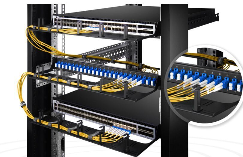
Patch Panel Recommendations
As a patch panel offers people easy cable management, it has been widely acknowledged by more and more users and expertise. When choosing a patch panel, a lot of factors can be considered, like types and designs. I would like to recommend you patch panels from there perspectives, that is, cabling system, port density, and space saving.Cabling System of Patch PanelAs we all know, the patch panel used in fiber cabling system is called fiber patch panel and the one used in copper cabling systems named copper patch panel. As far as I am concerned, the fiber patch panel deserves the higher price since it is a lot easier to install. However, copper patch panel can also be your first choice as it is cost-efficient and durable, like the Cat6 patch panel introduced in the next part.1U High 19" fiber patch panel is easy to install for better deployment and expand your network for interconnection and cross-connection inside the rack mount and cabinet. It has 24 ports and is available with two adapter types: SC and LC duplex.Specially designed for Gigabit Ethernet applications, Cat6 Ethernet patch panel meets and even exceeds the TIA/EIA 568 industry specification, and are compatible with all kinds of Cat6 cables and related accessories. Besides, Cat6 patch panels feature high-density and offer the performance required for present and next generation data communications networks and applications.Port Density of Patch PanelPort density seems to be a main concern when choosing a patch panel. The patch panel with more ports enables more connectivity. Common patch panels are always designed in 8 or 12-port configurations. While high-density patch panels are available in flat and angled designs with 24 or 48 ports configurations. High-density patch panel is suitable for installations with limited space.Take the Cat6 Ethernet patch panels we mentioned above as an example, as high-density patch panels, they are available in 12-port, 24-port, 48-port configurations, and feature enhanced front and rear labeling mark for easy circuit identification. In addition, the cat6 patch panel provided by FS.COM contains user-friendly number coding and removable rear cable manager which is conducive to uninstall and install.Space Saved by Patch PanelIn general, I, myself, prefer wall mount patch panel to rack mount patch panel, because it is installed above the floor, sparing much space for other equipment standing on the ground.Wall mount patch panel provided by FS.COM possesses number labeling for easy outlet identification, and is used to provide the critical connection between various fiber cables and optical equipment fixed on the customer’s house or office, offering networking and fiber distribution from the wiring closet to the user’s terminal equipment. Furthermore, it can be fixed quickly and easily to the wall using four screws.ConclusionHope you have saved a lot of time and energy by checking out the list we have above. However, another aspect not mentioned is the budget, as many people would struck in a dilemma that whether to choose a patch panel only for now or the expensive one for future. Considering this, you can first choose what function and performance you actually need, then compare the price of the same type of patch panel between different vendors. Here I can assure you that FS.COM can provide you with best quality and reasonable price. If you have puzzles, please do not hesitate to contact us.
2018.05.15
コメント(0)
-

2 * 8 Port Gigabit Switch or 1 * 16 Port Gigabit Switch
In computer networking, an Ethernet switch is a LAN interconnection device that serves as a bridge between multiple equipment and a Local Area Network (LAN). Ethernet switches are categorized into two main types – modular and fixed configuration. Fixed configuration switches have a fixed number of ports and are not expandable. You can select the switches based on number of ports. The larger the network, the greater number of ports you’ll need. Fixed configuration switches are generally available in 5, 8, 10, 16, 24, 28, 48, and 52-port configurations. Some people may question that is it a good idea to purchase two 8-port switches other than one 16-port switch since the price of two 8-port switches is much lower than that of one 16-port switch? 2 * 8 Port Gigabit Switch VS 1 * 16 Port Gigabit Switch—a good question worthy of discussing.2 * 8 Port Gigabit Switch VS 1 * 16 Port Gigabit SwitchThis question is very common and can be subjective according to the urgency of uptime, financial budget, network management and space involved. If most variables are not a problem, then, the answer is YES. Taking two switches from different vendors as an example, there is a wide gap between their price.S1130-8T2F Managed PoE+ SwitchFS.COM S1130-8T2F managed PoE+ switch comes with 8x 10/100/1000Base-T RJ45 Ethernet ports. It can supply power to network equipment such as weather-proof IP cameras with windshield wiper and heater, high-performance AP and IP telephone. This managed PoE+ switch is highly flexible, the transmission distance of the SFP fiber port can be up to 120km, and with high resistance to electromagnetic interference. It also features superior performance in stability, environmental adaptability and the price of it is $159.Intellinet 16-Port Gigabit Ethernet PoE+ Web-Managed SwitchIntellinet 16-Port gigabit Ethernet PoE+ web-managed switch with 2 SFP ports is sold at $501. Equipped with sixteen Gigabit Ethernet ports, all of which support 802.3at/af Power over Ethernet (PoE/PoE+), this switch can power wireless LAN access points and bridges, VoIP (Voice over Internet Protocol) telephones, IP surveillance cameras.Apart from price, there are other elements need to be considered. If the entire network depends on a single switch and, unfortunately the unit undergoes a catastrophic failure, the whole network would break down. However, if one of the 2 switches fails, only half the network is down but still able to limp along until there is a replacement. The only shortcoming is that you will lose two ports by connecting them, which means that you will have a 14-port switch if you buy two 8 ports.If you need to expand in the future, it’ll be nicer to work with a 16-port switch instead of a couple 8's. In smaller setups and homes, you can hardly notice the difference between the two, because you seldom have lots of transfers all at the same time and all destined for ports on the opposite switch. While in larger data centers, it can make a difference as you are constricting data flow by forcing 7 ports through one port to get to the other switch.ConclusionGigabit Ethernet transmitting at approximately one gigabit per second, as well as fiber optic cable are all products created in line with people’s desire for faster broadband. Most people turn to gigabit switches as they are easy to use, provide plug and play installations and can save the power consumption. After analyzing the issue—2 * 8 Port Gigabit Switch VS 1 * 16 Port Gigabit Switch, I sincerely hope it can help you make a right choice.
2018.05.09
コメント(0)
-

Introduction of Media Converter
If you want to realize the farther distance connectivity than the actual length the copper cabling you already have can offer, what should you do? Much worse is that no switch is available. Don’t be nervous. The easy solution offered by media converter will be illustrated in this article. Are you poised to have a close understanding of the small device which have blown every people’s minds?Media ConverterMedia converter is a cost-effective and flexible networking device that can connect various fiber optic cable such as multimode, single mode or single strand fiber cable and translates signals between fiber optic cabling and another type of cabling media such as cat6 Ethernet cable. If the distance between two network devices is greater than the copper cabling’s transmission distance, the fiber optic connectivity is required, and can be achieved by a media converter. Fiber connections can greatly extend the reach and reduce electromagnetic interference. Media converters were introduced to the industry in the 1990s, and played an important part of fiber types of cabling system in connection with existing copper-based wiring system. They are also used in metropolitan area network (MAN) access and data transport services to enterprise customers.There are a wide variety of copper-to-fiber and fiber-to-fiber media converters available that support different network protocols, data rates, cabling and connector types.Fiber to Fiber Media ConvertersOne of the key applications for fiber to fiber media converters is to connect between the two network types at the physical network layer. Fiber-to-fiber media converters provide connectivity between dual fiber and single-fiber optic cables. In addition, fiber-to-fiber media converters support conversion from one wavelength to another, including standard wavelengths (1310, 1550) and CWDM wavelengths. It can also extend a MM network across SM fiber with distances up to 140km in a cost-effective way. Fiber-to-fiber media converters are typically protocol independent and available for Ethernet, and TDM applications.Copper-to-Fiber Media ConvertersSupporting the IEEE 802.3 standard, Ethernet copper-to-fiber media converters provide connectivity for Ethernet, Fast Ethernet, Gigabit and 10 Gigabit Ethernet devices. Some converters support 10/100 or 10/100/1000 rate switching, enabling the integration of equipment of different data rates and interface types into one seamless network. The copper-to-fiber conversion carried out by a media converter allows two network devices having copper ports to be connected across long distances by means of fiber optic cabling.For twisted pair ports( RJ-45 ports), they can transfer signal of SFP port into signal of RJ-45 port for transmission. SFP port is mainly connected with upstream equipment while RJ45 port is connected to the downstream device.ConclusionIn the data center, fiber media converters pose as an alternative solution for switches. Next time you are in this condition, don’t hurry to throw the copper cable away, just an easy click on FS.COM, then all mess will be eliminated. Choose a suitable media converter and it will be delivered quickly to your address. The media converter provided by FS.COM is very small so won't occupy too much space and can be deployed in a variety of networks and applications.
2018.05.05
コメント(0)
-

Which One to Choose? Fiber or Copper Patch Panel?
It seems that you haven’t figured out what a patch panel is. A patch panel is a mounted hardware assembly that contains ports used to connect and manage fiber or copper optic cables going in and out. Patch panels are also known as patch bays, patch fields or jack fields which are usually installed on enclosures or racks to simplify connections. If it breaks down, the entire system may fail. Patch panels can be assorted based on the number of ports they contain. They can be used in fiber and copper cabling systems. Here we have fiber and copper patch panels.Fiber vs. Copper Patch PanelFiber patch panels require two ports for a pair of wires. One port is responsible for the transmitting end while the other looks after the receiving end. The fact that fiber patch panels tend to be faster than copper does not make sense in the condition where the main function of a patch panel is to direct signal traffic, not to send the signal at a particular speed. When installing the panel, a fiber optical cable needs to be split at one end in order to gain access to the individual fibers. The separated fibers are fed into different ports, each of which has a fiber optical adapter. These adapters can then be used to plug individual fibers into other devices. The loss caused by interface may be noticeable. Besides, if the fiber interface doesn’t connect perfectly, you may not get it work successfully.Copper patch panels have the 110-insulation displacement connector style on one side and 8-pin modular ports on the other. Wires coming into the panel are therefore terminated to the insulation displacement connector. On the opposite side, the 8-pin modular connector plugs into the port which corresponds to the terminated wires. With the copper patch panel, each pair of wires has an independent port. And when the front copper touches the copper in the back, a little bit of the signal is lost but not enough to worry about. And copper is easy to interface- even if the connector doesn’t match perfectly, as long as wire A touches wire B, you get a connection.Fiber and Copper Patch Panels Provided by FS.COM1U High 19" fiber patch panel is easy to install for better deployment and expand your network for interconnection and cross-connection inside the rack mount and cabinet. It has 24 ports and is available with two adapter types: SC and LC duplex.Cat6 patch panels deliver a steady 250 MHz connection to copper Gigabit switches, ideal for Ethernet, Fast Ethernet and Copper Gigabit Ethernet (1000Base-T) network applications. They are available in 6-port and 8-port module groupings, in 8, 12, 24, and 48-port sizes. The cat6 patch panel provided by FS.COM contains user-friendly number coding and removable rear cable manager which is conducive to uninstall and install. Ordered number coding enables it easy to install and distinct cable. In addition, management bar and numbers are easy for cabling neat, organized and connection identification.ConclusionIt is not easy to tell which fiber patch panel is better unless in a given situation. The copper and fiber patch panel both have their own advantages and shortcomings when applied to different systems. FS.COM also provides many kinds of patch panels, each representing a cost-effective solution for your application. And they can adapt to your changes and adds on the equipment.
2018.05.02
コメント(0)
-

Big Secret in Fiber Optic Cables
Have you noticed the changes happened in just a few years ago?— The faster internet speed? The thinner computer screen? Or the smaller computer case? Well, one special thing that I want you know is the fiber optic cable. The emergence of it has made the copper cable gradually disappear in front of the public. Today, we will center on the topic that how and why it happens in our life, and provide you with some hints about this magic wire.What Is Fiber Optic CableFiber optic cables carry communication signals through pulses of light produced by small lasers or light-emitting diodes (LEDs). Compared to wired cables, fiber optic cables provide higher bandwidth and can transmit data over longer distances.The cable consists of one or more strands of glass, each only slightly thicker than a human hair. The center of each strand is called the core which provides the pathway for light to travel. The core is wrapped by a layer of glass called cladding that reflects light inward to avoid loss of signal and allow the light to pass through bends in the cable.Fiber Optic Cable TypesThe two primary types of fiber cables are called single mode and multi-mode fiber. Single mode fiber uses very thin glass strands and a laser to generate light while multi-mode fibers use LEDs. The core diameter of single mode fiber is 9μm, and multi-mode is 62.5μm or 50μm.Single mode fiber networks often use Wave Division Multiplexing (WDM) techniques to increase the amount of data traffic that can be sent across the strand. WDM allows light at multiple different wavelengths to be combined (multiplexed) and later separated (de-multiplexed), effectively transmitting multiple communication streams via a single light pulse.ItemsSingle mode fiberMulti-mode fiberTransmitting distanceLongShortData transmission rateHighLowLamp-houseLaserLight-emitting diodes(LEDs)Signal lossSmallLargeDifficulty of accessHardEasyCostsHighLowWhen making a decision between single mode and multi-mode fiber cables, the first element to consider is the fiber distance you actually need. For example, in a data center, multi-mode fiber cables is enough for the distance of 300-400 meters. While in applications that require distance up to several thousands of meters, the single mode fiber is the best choice. And in applications which can use single mode and multi-mode fiber, other factors like cost and future upgrade requirements should be taken into consideration for your choice.How To Install Fiber Optic CableFiber optic cable has now penetrated into all aspects of our lives. Understanding the basic knowledge of fiber optic cable installation may help us build a fiber optic network system with high performance and stability. Therefore, one cannot be too cautious when installing fiber optic cables. The end of each cable must be ground and connected to the optical interface through an electric grill or chemical chlorination process to ensure that the optical channel is not obstructed. Moreover, fibers cannot be pulled too tight or form a right angle. Remember to avoid moisture, operate within the cable’s temperature range, and bear in mind the bend radii, crush load and use load along with vertical rise distance.
2018.04.14
コメント(0)
-

You Really Know About QSFP+ Transceivers ?
In the last passage, we have gained a deep and comprehensive understanding of 10 Gigabit Ethernet. Next, we will shed light on 40 Gigabit Ethernet which was introduced by the IEEE 802.3ba in 2010. 802.3ba is the designation given to the higher speed Ethernet task force which completed its work to modify the 802.3 standard to support speeds higher than 10 Gbit/s. 40G is slowly taking the place of the 10G network market as the latter is becoming out-dated due to its slow speed and other shortcomings. Therefore, it is beneficial to study the 40G transceivers in detail.40G Transceiver: QSFP+ ModuleA 40G optical module is a derivative product capable of delivering high density ports and considerable data transmission speed. It is a high performance, hot-pluggable interconnect solution finding its rampant use in data centers. An integrated model of four independent transmit and receive signals work coordinately to deliver the high density but power-efficient 40G Ethernet connectivity. The 40G applications, apart from in data centers, are also being used widely in high performance computing networks, enterprise core and distribution layers, and telecom operators. The new demands of 40G transceiver modules pushed the high-speed optical transceiver market to grow. This article would put emphasis on introducing 40G optical transceiver, especially the QSFP+ module.What’s 40G QSFP+ Module?The 40G QSFP+ module is a hot-swappable, parallel fiber optical module. The 40G QSFP+ transceiver complies with the Ethernet, Fibre Channel, InfiniBand, and SONET/SDH standards. It adopts four 10Gbit/s transmission channels to transmit data and the transmission of four channels can get 40Gbps at the same time. In addition, 40G QSFP+ connector can be either duplex LC or 12-fiber MTP/MPO connector.Types of 40G QSFP+ ModuleIn this part, three kinds of 40G QSFP+ transceivers will be introduced respectively, that is, QSFP 40G SR4, QSFP BiDi, QSFP 40G LR4.QSFP 40G SR4, Short-reach (SR) transceivers for 40G connectivity in a QSFP form factor, uses independent transmitter and receiver sections, each with 4 parallel fiber strands. It can transmit 150 meters over OM4 MMF. For a 40G connection, 8 fiber strands are required, and 12-fiber MPO connectors are used.The QSFP BiDi transceiver is a short-reach optical transceiver that delivers 40 Gbps over a duplex OM3 or OM4 MMF connection, which can reach 100 meters on OM3 or up to 150 meters over OM4. It has two 20G channels, each transmitted and received simultaneously on two wavelengths over a single MMF strand.The QSFP 40G LR4 Module supports link lengths of up to 10km over a standard pair of G.652 single-mode fiber with duplex LC connectors. The 40 Gigabit Ethernet signal is carried over four wavelengths. Multiplexing and demultiplexing of the four wavelengths are managed within the device.QSFP+ TypeWavelength(nm)Fiber TypeConnector Type Max Transmission LengthQSFP 40G SR4850MMFMTP/MPO150mQSFP BiDi832-918MMFLC150mQSFP 40G LR41310SMFLC10kmConclusionAs is shown in the table, there are many types of QSFP+ transceivers. We(www.fs.com) offer a wide range of 40GBASE QSFP+ optical modules that are compatible with major brand network devices, and can also provide OEM customized services. All of our 40G QSFP+ optical modules are tested in multiple performances at the test center for superior performance.
2018.04.13
コメント(0)
全33件 (33件中 1-33件目)
1


