



2013.09.08

カテゴリ: RF-1401D/RF-1405/RF-1700
先日9/1に実施したRF-B10のFMバンドパスフィルター調整が非常にうまくいったので、それに倣ってRF-1700のFM受信部を再調整しました。ついでに周波数変換用のトランジスタ×3と中間周波数増幅用と思われるトランジスタ1つも交換しました。
まずFMのバンドパスフィルター回路です。
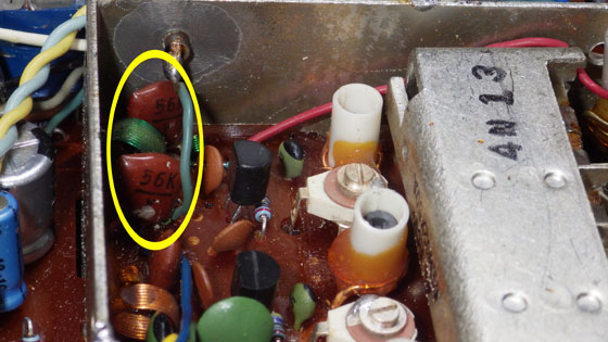
黄色い○の中にあるのがバンドパスフィルターを構成していると推定したコンデンサで、見た感じはシルバードマイカ:56pFです。手許にシルバードマイカの10pFと100pFがあったので、基板の裏側へ10pFをそれぞれ付けてトータル66pFにしました。もう一個この画像では取り外してありますが3.5pFのセラミックコンデンサを手持ちの6pFと交換しました。これも基板の裏側に付いています。
続いてトランジスタ交換したPSB-Hi、AirとFM周波数変換部分で、交換前は撮影していなかったので交換後の画像です。
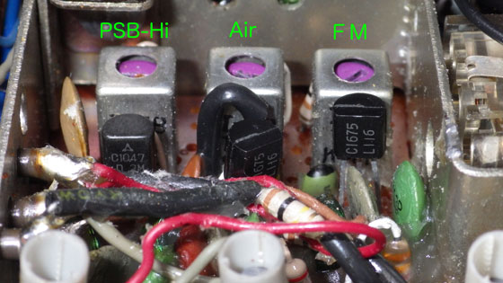
2SC920 → 2SC1675、2SC921 → 2SC1047へ交換しました。
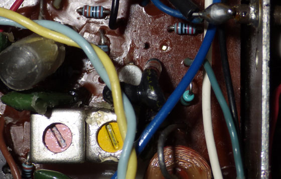
そして中間周波数増幅段のトランジスタ交換です。交換前がこちら。2SC920が上下逆さまに写っています。
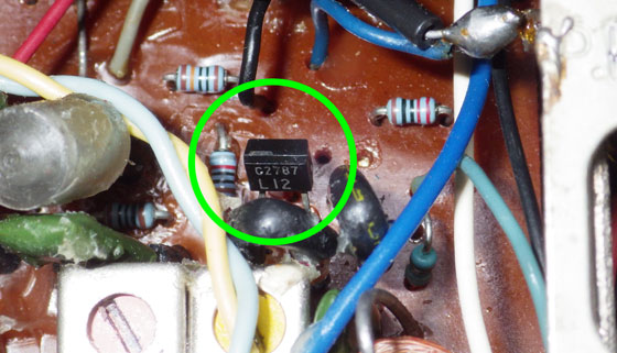
これを2SC2787(2SC1675の小型パッケージ)へ交換しました。緑色の丸で囲った奴です。
そして今このトピックを書いている間に、バンド切り替えスイッチの隙間にあるトランジスタを1つ見つけました。2SC920なんですが短波帯の高周波増幅かなぁ? 中波帯の周波数変換も兼ねているのかなぁ? 昨日の内に見つけていれば交換したのに残念です。
最後に肝心の受信結果(網線入りガラス越しの室内での受信です)は、今まで全く入感しなかったFMナックファイブがRF-2900と同程度に了解度2〜3で受信出来るようになりました。
良い結果が出て良かった〜。
まずFMのバンドパスフィルター回路です。
黄色い○の中にあるのがバンドパスフィルターを構成していると推定したコンデンサで、見た感じはシルバードマイカ:56pFです。手許にシルバードマイカの10pFと100pFがあったので、基板の裏側へ10pFをそれぞれ付けてトータル66pFにしました。もう一個この画像では取り外してありますが3.5pFのセラミックコンデンサを手持ちの6pFと交換しました。これも基板の裏側に付いています。
続いてトランジスタ交換したPSB-Hi、AirとFM周波数変換部分で、交換前は撮影していなかったので交換後の画像です。
2SC920 → 2SC1675、2SC921 → 2SC1047へ交換しました。
そして中間周波数増幅段のトランジスタ交換です。交換前がこちら。2SC920が上下逆さまに写っています。
これを2SC2787(2SC1675の小型パッケージ)へ交換しました。緑色の丸で囲った奴です。
そして今このトピックを書いている間に、バンド切り替えスイッチの隙間にあるトランジスタを1つ見つけました。2SC920なんですが短波帯の高周波増幅かなぁ? 中波帯の周波数変換も兼ねているのかなぁ? 昨日の内に見つけていれば交換したのに残念です。
最後に肝心の受信結果(網線入りガラス越しの室内での受信です)は、今まで全く入感しなかったFMナックファイブがRF-2900と同程度に了解度2〜3で受信出来るようになりました。
良い結果が出て良かった〜。
お気に入りの記事を「いいね!」で応援しよう

[RF-1401D/RF-1405/RF-1700] カテゴリの最新記事
-
RF-1700のロッドアンテナ、今度こそ直しま… 2023.02.11
-
RF-1700のロッドアンテナ:やり直します😢 2023.02.09
-
画像を追加しました:RF-1700-2台目のロッ… 2023.02.08
Re:RF-1700をもう一度調整しました(09/08)
Joydip san さん
Thanks for your interesting blog on RF1700. Iam also trying to repair an RF1700 at present. Medium wave, short wave are not working but FM and Airband are ok. So I think maybe the 2SC920 conversion transistor is faulty. Hoping to replace it with a BF241.
(2016.11.11 08:39:36)
Re[1]:RF-1700をもう一度調整しました(09/08)
Dear Joydip san, Thnks to your comment.
>Thanks for your interesting blog on RF1700. Iam also trying to repair an RF1700 at present. Medium wave, short wave are not working but FM and Airband are ok. So I think maybe the 2SC920 conversion transistor is faulty. Hoping to replace it with a BF241.
I searched BF241. According to your RF-1700 condition, it seems to be a good choice to replace converting 2SC920 to BF241. Hope ypour work is done successfully!
-----
(2016.11.11 10:19:01)
>Thanks for your interesting blog on RF1700. Iam also trying to repair an RF1700 at present. Medium wave, short wave are not working but FM and Airband are ok. So I think maybe the 2SC920 conversion transistor is faulty. Hoping to replace it with a BF241.
I searched BF241. According to your RF-1700 condition, it seems to be a good choice to replace converting 2SC920 to BF241. Hope ypour work is done successfully!
-----
(2016.11.11 10:19:01)
Re[1]:RF-1700をもう一度調整しました(09/08)
Re:RF-1700をもう一度調整しました(09/08)
Joydip さん
Dear friend. Thank you for your prompt reply. Please forgive me for writing in English because I only know a few Japanese words. I am not an engineer but like repairing and collecting old radios. I think repairing my RF1700 is very difficult. I have the circuit diagram for this radio, so found that the 2SC920 transistor collector was showing abnormal 0 volt reading on the circuit board. I thought that maybe the transistor is defective, so I desoldered it. However, it is testing normal and showing as an NPN transistor on my meter. When I tested the radio circuit board again without the transistor, it is showing voltages at base and emitter but still 0 volts where the collector connection is. So Iam puzzled and trying to find if there is a break in the circuit board somewhere or maybe an open resistor. Please let me know if you have any suggestions. Many thanks, Joydip.
(2016.11.12 08:52:06)
Re[1]:RF-1700をもう一度調整しました(09/08)
Joydip さん, thanks again for your information.
> I only know a few Japanese words.
Please don't mind it!
> so found that the 2SC920 transistor collector was showing abnormal 0 volt reading on the circuit board. I thought that maybe the transistor is defective, so I desoldered it. However, it is testing normal and showing as an NPN transistor on my meter. When I tested the radio circuit board again without the transistor, it is showing voltages at base and emitter but still 0 volts Joydip.
Still have 0 voltage on collector...In such case, I'm doubtful that S4-6 has a loosen contact. S4-6 is the power supply line to MW,MB and SW's circuit.
So, won't you check S4-6's connection, breaking wire and breaking pattern , or some shortage caused by bad soldering. Please watch them.
----- (2016.11.12 10:11:17)
> I only know a few Japanese words.
Please don't mind it!
> so found that the 2SC920 transistor collector was showing abnormal 0 volt reading on the circuit board. I thought that maybe the transistor is defective, so I desoldered it. However, it is testing normal and showing as an NPN transistor on my meter. When I tested the radio circuit board again without the transistor, it is showing voltages at base and emitter but still 0 volts Joydip.
Still have 0 voltage on collector...In such case, I'm doubtful that S4-6 has a loosen contact. S4-6 is the power supply line to MW,MB and SW's circuit.
So, won't you check S4-6's connection, breaking wire and breaking pattern , or some shortage caused by bad soldering. Please watch them.
----- (2016.11.12 10:11:17)
Re[5]:RF-1700をもう一度調整しました(09/08)
Joydip さん
Dear friend, thank you for your valuable suggestion. I found what I think is a short circuit between pins 4 and 5 only on the right hand side of S5, which is the MW bandswitch when viewed from the back of the radio.These two pins remain in contact even when I press the switch down,so I think this is the result of a short circuit somewhere else on the PCB. Anyway I will now look to see if I can find where the short is coming from. I hope it is not coming from inside the MW switch as I will not be able to repair that. Best regards, Joydip.
(2016.11.13 09:33:11)
Re[6]:RF-1700をもう一度調整しました(09/08)
Hello Joydip さん
>I found what I think is a short circuit between pins 4 and 5 only on the right hand side of S5, which is the MW bandswitch when viewed from the back of the radio.These two pins remain in contact even when I press the switch down,
That may be a reason of faulty receiving on MW or so. But I'm afraid it's not a power source line to 2SC920.
so I think this is the result of a short circuit somewhere else on the PCB. Anyway I will now look to see if I can find where the short is coming from. I hope it is not coming from inside the MW switch as I will not be able to repair that.
I found that DC power source is T5-455kHz-IFT, And via T5, S4~S8's 11th pins on the right side, from the back of the radio, always indicates 8.9V as 2SC920 collector.
Talking about pins 4 and 5 only on the right hand side of S5, I recommend you to have a very close look around the very 4th pin and 5th pin on the left.
If the 5th pin in the left is short to connect on adjoining positive voltage line, 4 and 5 pin in the right should always connected.
These are few more suggestions of mine. Good Luck!
----- (2016.11.13 11:02:52)
>I found what I think is a short circuit between pins 4 and 5 only on the right hand side of S5, which is the MW bandswitch when viewed from the back of the radio.These two pins remain in contact even when I press the switch down,
That may be a reason of faulty receiving on MW or so. But I'm afraid it's not a power source line to 2SC920.
so I think this is the result of a short circuit somewhere else on the PCB. Anyway I will now look to see if I can find where the short is coming from. I hope it is not coming from inside the MW switch as I will not be able to repair that.
I found that DC power source is T5-455kHz-IFT, And via T5, S4~S8's 11th pins on the right side, from the back of the radio, always indicates 8.9V as 2SC920 collector.
Talking about pins 4 and 5 only on the right hand side of S5, I recommend you to have a very close look around the very 4th pin and 5th pin on the left.
If the 5th pin in the left is short to connect on adjoining positive voltage line, 4 and 5 pin in the right should always connected.
These are few more suggestions of mine. Good Luck!
----- (2016.11.13 11:02:52)
Re[7]:RF-1700をもう一度調整しました(09/08)
Joydip さん
Hello again Shigechan
Thanks once more for giving me some fresh suggestions. I checked the S4-8 switches as per your advice and did not seem to find any fault. So I replaced TR7 2SC920 with a BF241 carefully. When I switched the radio on, I got a collector voltage of 4.5 v but still no AM reception. Surprisingly when I switched the radio off, the collector voltage jumped to 9 volts. I then thought there has to be a short circuit somewhere along the power supply line of BF241 and decided to look at T5, the first 455 kHz IFT. I desoldered it and found that the primary winding is showing continuity with the secondary winding. If I am correct, there should be no connection between primary and secondary and this is causing a short ? Please let me know if you agree. I checked AM AGC diode D4 and it is showing correct voltage drop of 0.3 volts out of circuit. Best regards.
(2016.11.17 10:19:27)
Thanks once more for giving me some fresh suggestions. I checked the S4-8 switches as per your advice and did not seem to find any fault. So I replaced TR7 2SC920 with a BF241 carefully. When I switched the radio on, I got a collector voltage of 4.5 v but still no AM reception. Surprisingly when I switched the radio off, the collector voltage jumped to 9 volts. I then thought there has to be a short circuit somewhere along the power supply line of BF241 and decided to look at T5, the first 455 kHz IFT. I desoldered it and found that the primary winding is showing continuity with the secondary winding. If I am correct, there should be no connection between primary and secondary and this is causing a short ? Please let me know if you agree. I checked AM AGC diode D4 and it is showing correct voltage drop of 0.3 volts out of circuit. Best regards.
(2016.11.17 10:19:27)
Re[8]:RF-1700をもう一度調整しました(09/08)
Hello Joydip さん
> and decided to look at T5, the first 455 kHz IFT. I desoldered it and found that the primary winding is showing continuity with the secondary winding. If I am correct, there should be no connection between primary and secondary and this is causing a short ? Please let me know if you agree. I checked AM AGC diode D4 and it is showing correct voltage drop of 0.3 volts out of circuit. Best regards.
>
Thank you for your detailed information. Primary winding and secondary winding of T5 should be insulated if you removed T5 from the print board, So, there must be some faulty short.
Won't you try to remove the shield case of T5? I used to find that soldered point was connected to short to the shield case. It's quite doubtful.
----- (2016.11.17 16:03:49)
> and decided to look at T5, the first 455 kHz IFT. I desoldered it and found that the primary winding is showing continuity with the secondary winding. If I am correct, there should be no connection between primary and secondary and this is causing a short ? Please let me know if you agree. I checked AM AGC diode D4 and it is showing correct voltage drop of 0.3 volts out of circuit. Best regards.
>
Thank you for your detailed information. Primary winding and secondary winding of T5 should be insulated if you removed T5 from the print board, So, there must be some faulty short.
Won't you try to remove the shield case of T5? I used to find that soldered point was connected to short to the shield case. It's quite doubtful.
----- (2016.11.17 16:03:49)
Re[9]:RF-1700をもう一度調整しました(09/08)
Joydip さん
I was able to remove the can from the T5 IFT today after heating it with a hairdryer to melt the wax. The can was not shorting the IFT terminals as the primary -secondary short is still there after removing the can.Also the very fine wire to one terminal is broken in the middle. I do not think I can find this IFT easily in the UK because it has six legs and is 11mm by 7mm,part no. is I-2B I26M HEL3. The spare 455 kHz IFTs being sold here in Europe all seem to have five legs only. So I will have to wait till I can find a replacement before knowing if this is indeed the cause of all the AM bands without reception. Thanks again my friend and bye for now.
(2016.11.18 09:33:24)
(2016.11.18 09:33:24)
Re[10]:RF-1700をもう一度調整しました(09/08)
Hello Joydip さん
I understood and believe this is the reason why AM bands shouldn't work. Broken wire is too fine to connect again. So, Good luck on you . Bye!
----- (2016.11.18 17:38:00)
I understood and believe this is the reason why AM bands shouldn't work. Broken wire is too fine to connect again. So, Good luck on you . Bye!
----- (2016.11.18 17:38:00)


【毎日開催】
15記事にいいね!で1ポイント


PR
コメント新着

shigechan2008
shigechan2008のブログへようこそ ディープでオタクな硬派(^o^)?のブログです。古いラジオの修復記事がメイン?ですけど、最近はサボり気味😵 アップル関連や食べ物も宜しくお願いします🍉🍍
フリーページ
カテゴリ
カテゴリ未分類
(0)写真
(601)カメラ
(114)TV/ディスプレイ/オーディオ/ビジュアル
(194)iPod各種
(38)日用品
(318)SCD-777ES
(5)音楽
(23)健康
(89)携帯電話、携帯通信、OS
(1040)パソコン、タブレット関係
(1454)セキュリティ
(133)各種放熱管理
(34)工具/工作用品
(38)半導体、電子部品
(158)時計
(89)食べ物
(849)商品レビュー
(488)その他
(456)鉄道関連
(304)ブログ設定
(17)アマチュア無線
(17)ラジオ・受信機
(138)RF-2200
(31)RF-2900
(53)RF-2600/RF-2800
(18)RF-2800B
(15)RF-2900LBS
(59)RF-6300LBS/RF-B300
(19)RF-B10/RF-B11/RF-B20
(28)RF-B40/RF-B45/RF-B55/RF-B65
(42)テレコ、ラジカセ
(28)RF-1108/RF-1140
(8)RF-1150LB/RF-1130LB/RF-1130LBS
(25)RF-1180/RF-1180B
(17)RF-1650J/RF-1680L/RF-1630L
(13)RF-1401D/RF-1405/RF-1700
(33)RF-690/RF-850シリーズ/RF-858/RF-859
(70)RF-822/RF-622:お風呂ラジオ
(9)RF-080/RF-081/RF-082/RF-088
(39)RF-032D/RF-066/RF-079
(15)RF-788L/RF-096L/RF-818JB/RF-833L/RF-844
(32)RF-877/RF-727
(13)RF-888JB(GX300)
(65)R-109/R-505/R-905J/R-1052/R-77
(28)R-82/R-140/R-166/R-441B/R-8
(11)T-12/T-13/T-55/T-59
(13)T-81H/RF-1006M
(15)その他小型ラジオ
(31)ICF-5600/ICF-SW77,SW22/ICF-7500/SRS-F10
(27)ICR-4800
(7)RE-6250,R-1492
(8)キーワードサーチ
▼キーワード検索
購入履歴
詰め替え用 カビ予防剤 浴室用 バイオの職人 お風呂 掃除 安心 安全 塩素系不使用 お風呂カビ予防 カビ予防剤 日本製 環境に優しい バチルス菌 換気 【▲】/バイオの職人浴室用詰め替え
SHARP 互換品 FZ-Y30SF FZY30SF 互換フィルター 空気清浄機用フィルター 花粉 集塵 脱臭 一体型フィルター 純正品同等 (管理S) 送料無料
シャボン玉石けん 洗たく槽クリーナー 500g 【SB02665】
スジャータ こだわりのアイスコーヒー 無糖 1000ml紙パック×6本入| 送料無料 珈琲 コーヒー 1l 1L 無糖コーヒー 無糖 アイスコーヒー
フマキラー キッチン用 アルコール除菌スプレー つめかえ用 大容量(5L)【フマキラー アルコール除菌シリーズ】[除菌スプレー/抗菌/まな板/キッチン/消臭/食器/掃除]
SHARP 互換品 FZ-Y30SF FZY30SF 互換フィルター 空気清浄機用フィルター 花粉 集塵 脱臭 一体型フィルター 純正品同等 (管理S) 送料無料
シャボン玉石けん 洗たく槽クリーナー 500g 【SB02665】
スジャータ こだわりのアイスコーヒー 無糖 1000ml紙パック×6本入| 送料無料 珈琲 コーヒー 1l 1L 無糖コーヒー 無糖 アイスコーヒー
フマキラー キッチン用 アルコール除菌スプレー つめかえ用 大容量(5L)【フマキラー アルコール除菌シリーズ】[除菌スプレー/抗菌/まな板/キッチン/消臭/食器/掃除]
カレンダー
テンポスホールディ…
 New!
エム坊さん
New!
エム坊さん
北海道・北竜ひまわ… New! inkyo7さん
源氏物語〔35帖 柏木…
New!
USM1さん
「元に戻らないうち…
New!
こたつねこ01さん
小田急電鉄 小田原線…
New!
鉄人騎士。さん
この夏の”新型コロナ…
New!
藻緯羅さん
葉月は和風月名~~~ New! セミ・コンフィさん
注文キャンセル New! エンスト新さん
ジッとじっとして・…
New!
ナイト1960さん
都内公園~S川散策日…
New!
★黒鯛ちゃんさん
New!
エム坊さん北海道・北竜ひまわ… New! inkyo7さん
源氏物語〔35帖 柏木…
New!
USM1さん「元に戻らないうち…
New!
こたつねこ01さん小田急電鉄 小田原線…
New!
鉄人騎士。さんこの夏の”新型コロナ…
New!
藻緯羅さん葉月は和風月名~~~ New! セミ・コンフィさん
注文キャンセル New! エンスト新さん
ジッとじっとして・…
New!
ナイト1960さん都内公園~S川散策日…
New!
★黒鯛ちゃんさん© Rakuten Group, Inc.
