赤外線送受信(アナログ)
赤外線送受信の実験その2(アナログチャンネル追加)
デジタル2チャンネル,アナログ1チャンネルの送受信を行うため,
アナログチャンネルを追加しました.
コンパイラはHITECH PICC-LITE です.
赤外線送信側のプログラム(PIC16F84A用)
#include "pic.h"
#include "delay.h"
main(){
unsigned char i,j;
TRISA=0b11110111; /* ch1,2: RA0,1 digital ,ch3: RA2 and RA3 analog */
TRISB=0b00000000;
while (1){
if(RA0) j=100; else j=50; /* ch1, RA0: on->100, off->50 cycle */
for (i=j; i>0; i--){
PORTB=0b11111111;
DelayUs(13);
PORTB=0b00000000;
DelayUs(13);
}
for (i=j; i>0; i--) DelayUs(26);
if(RA1) j=100; else j=50; /* ch2, RA1: on->100, off->50 cycle */
for (i=j; i>0; i--){
PORTB=0b11111111;
DelayUs(13);
PORTB=0b00000000;
DelayUs(13);
}
for (i=j; i>0; i--) DelayUs(26);
RA3=1; /* charge C for use of analog input */
for (i=100; i>0; i--) DelayUs(10);
RA3=0; /* set RA3 to 0 for discharge of C */
j=0; /* reset counter of j */
while(RA2){ /* count j */
DelayUs(2);
j++;
}
j=j+50;
for (i=j; i>0; i--){ /* ch3: RA2 pulse width varied from analog input */
PORTB=0b11111111;
DelayUs(13);
PORTB=0b00000000;
DelayUs(13);
}
for (i=j; i>0; i--) DelayUs(26);
for (i=255; i>0; i--) DelayUs(255); /* brank */
}
}
赤外線受信側のプログラム(PIC16F84A用)
#include "pic.h"
#include "delay.h"
unsigned char k, pw1, pw2;
void pwm(void){
if (k>=pw1) RB2=0; else RB2=1; /* 0->pw1:on, pw1->pw2:off */
k++;
if (k>pw2) k=0;
DelayUs(16);
}
main(){
unsigned char i,j;
TRISA=0b11111111;
TRISB=0b00000000;
k=0; pw1=0; pw2=100;
while (1){
// brank skip
i=0;
while (i<100){
if (RA0) i++; else i=0; /* RA0=1 nara cout up, RA0=0 de reset */
for (j=10; j>0; j--) pwm();
}
// ch1: digital output
while (RA0) pwm();
i=0;
while (!RA0) {
i++;
pwm();
}
if (i<75) RB0=0; else RB0=1;
// ch2: digital output
while (RA0) pwm();
i=0;
while (!RA0) {
i++;
pwm();
}
if (i<75) RB1=0; else RB1=1;
// ch 3: analog output, set PWM parameter
while (RA0) pwm();
i=0;
while (!RA0) {
i++;
pwm();
}
if (i-60<0) pw1=0; /* 60 count offset */
else if (i-60>pw2) pw1=pw2; else pw1=i-60;
}
}
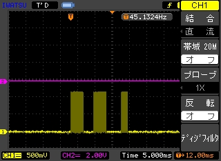
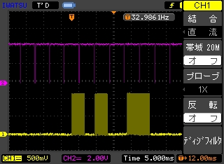
初期状態
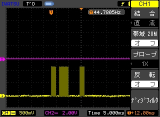
ch1に入力してパルス幅を小さくしたところ.
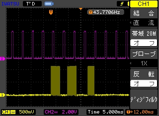
PWMによる出力その1
PWMによる出力その2
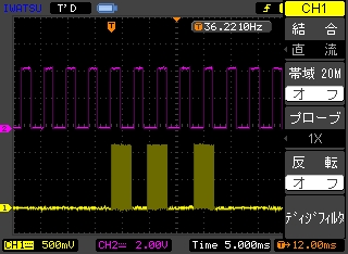
PWMによる出力その3
----追記----
インドアプレーン用に,PIC12F629用にプログラムを移植しました.
I/Oとチャンネルの割り当ては,リストを参照ください.
リチウムポリマー電池で動かすとなると電源電圧が3.7Vになるので,
内部RCによる発信では若干周波数が変わるようなので,タイミングの修正などしました.
あと,回路的に都合がいいように,ch1とch2の出力の正負論理を入れ替えました.
赤外線送信側のプログラム(PIC12F629用)
#include "pic.h"
#include "delay.h"
#define HDLY 10 // half delay time for IR mod., normal value (enough high osc) is 13 us
#define FDLY 20 // full delay time for IR mod., normal value (enough high osc) is 26 us
__CONFIG(INTIO & WDTDIS & BORDIS & MCLRDIS);
main(){
unsigned char i,j;
TRIS0=1; /* ch1: GPIO0 for digital input */
TRIS1=1; /* ch2: GPIO1 for digital input */
TRIS2=0; /* ch3: GPIO2 for analog input, for charging/discharging cap. */
TRIS3=1; /* ch3: GPIO3 for analog input */
TRIS4=0; /* GPIO4 for IR output */
CMCON=0x07;
while (1){
if(GPIO0) j=100; else j=50; /* ch1 out. GPIO0: on->100, off->50 cycle */
for (i=j; i>0; i--){
GPIO4=1;
DelayUs(HDLY);
GPIO4=0;
DelayUs(HDLY);
}
for (i=j; i>0; i--) DelayUs(FDLY);
if(GPIO1) j=100; else j=50; /* ch2 out. GPIO1: on->100, off->50 cycle */
for (i=j; i>0; i--){
GPIO4=1;
DelayUs(HDLY);
GPIO4=0;
DelayUs(HDLY);
}
for (i=j; i>0; i--) DelayUs(FDLY);
GPIO2=1; /* Cap charge */
for (i=100; i>0; i--) DelayUs(10);
GPIO2=0; /* set GPIO2 to 0 for Cap discharge */
j=0; /* reset counter j */
while(GPIO3){ /* count j */
DelayUs(2);
j++;
}
j=j+50;
for (i=j; i>0; i--){ /* ch3 out. GPIO4 for PWM */
GPIO4=1;
DelayUs(HDLY);
GPIO4=0;
DelayUs(HDLY);
}
for (i=j; i>0; i--) DelayUs(FDLY);
for (i=255; i>0; i--) DelayUs(255); /* brank */
}
}
赤外線受信側のプログラム(PIC12F629用)
#include "pic.h"
#include "delay.h"
#define FDLY 3 // full delay time for IR mod., normal value (enough high osc) is 26 us
__CONFIG(INTIO & WDTDIS & BORDIS & MCLRDIS);
unsigned char k, pw1, pw2;
void pwm(void){
if (k>=pw1) GPIO2=0; else GPIO2=1; /* 0->pw1:on, pw1->pw2:off */
k++;
if (k>pw2) k=0;
DelayUs(FDLY);
}
main(){
unsigned char i,j;
TRIS0=0; /* ch1: GPIO0 for digital output */
TRIS1=0; /* ch2: GPIO1 for digital output */
TRIS2=0; /* ch3: GPIO2 for pwm output */
TRIS3=1; /* GPIO3 for IR input */
CMCON=0x07;
k=0; pw1=0; pw2=85;
while (1){
// brank skip
i=0;
while (i<100){
if (GPIO3) i++; else i=0; /* RA0=1 nara cout up, RA0=0 de reset */
for (j=10; j>0; j--) pwm();
}
// ch1: digital output
while (GPIO3) pwm();
i=0;
while (!GPIO3) {
i++;
pwm();
}
if (i<75) GPIO0=1; else GPIO0=0;
// ch2: digital output
while (GPIO3) pwm();
i=0;
while (!GPIO3) {
i++;
pwm();
}
if (i<75) GPIO1=1; else GPIO1=0;
// ch 3: analog output, set PWM parameter
while (GPIO3) pwm();
i=0;
while (!GPIO3) {
i++;
pwm();
}
if (i-55<0) pw1=0; /* 55 count offset */
else if (i-55>pw2) pw1=pw2; else pw1=i-55;
}
}
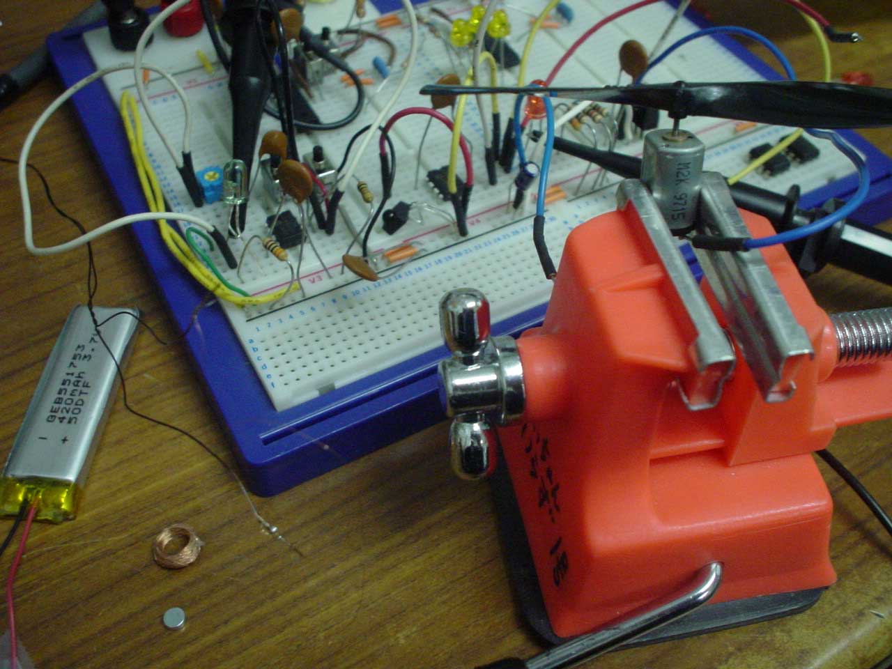
PWMによるモータ制御の動画
※ご注意
ノイズ対策などしてません.ご使用は個々の判断で.
---追記---
ちょっと追記します.
受信範囲から外れたとき,場合によってはモータが回りっぱなしになるので,
受信してないときはモータをOFFするようにプログラムを書き換えた方が良いです.
また,内部CRの発信回路を使っているので,発信周波数が電源電圧に依存します.
送信機と受信機で電圧が違ったり,電池が弱ってきたりするとプログラムが正常に動作しなくなってくるので,パルス幅による条件判断を工夫したほうが良いです.
例えば,最初に固定長のパルスを送り,受信側でそれを基準値に使い,その後に変調したパルスを送るようにすればより正確な送受信ができます.
ジャンル別一覧
人気のクチコミテーマ
-
-

- 楽天ラッキーくじ
- 楽天ラッキーくじ更新情報(2024/11/…
- (2024-11-26 14:12:27)
-
-
-
- しんくぱっど
- X270のキーボードを交換したい
- (2024-11-18 06:40:01)
-
-
-

- 楽天アフィリエイト♪
- 2.5SSDと外付け2.5RAIDケースで
- (2024-12-02 19:00:08)
-
© Rakuten Group, Inc.


