
Discuss Scratch

- Discussion Forums
- » Advanced Topics
- » 3D on scratch, And how it's professionally accomplished
![[RSS Feed]](https://cdn.scratch.mit.edu/scratchr2/static/__5b3e40ec58a840b41702360e9891321b__//djangobb_forum/img/feed-icon-small.png "[RSS Feed]")
- GL00B
-
 Scratcher
89 posts
3D on scratch, And how it's professionally accomplished
Hello, I'm GL00B, and in this short explanation I'll provide you with one of the BEST explanations of 3D, in our beloved scratch. Read on!
INTRODUCTION
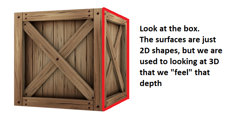
3D on scratch, or in general, has always been a controversial topic. we need to exactly define what “3D” we thrive to explain in this tutorial. Many projects tend to call themselves “3D”, But Are they? You see, if you dive deeper into this topic, EVERY 3D you see on your “2D” screen is just an illusion. even modern games, they are all 2D illusions that our brain is tricked into thinking that they're 3D. We are so used to 3D objects in real life that we just feel the depth in those 2D shapes that appear on the screen, making us feel like we indeed are looking at real 3D objects.
But how is that case with scratch? is scratch capable of making these illusions ?
Yep , scratch indeed is VERY capable of. In fact, you can create 3D illusions on flat 2D paper, and scratch, with it's lovely interactive stage, is no excepetion of that! We need to understand how to reach that illusion, and then we can actually start thinking right on how to start making our 3D project.
TYPES OF “3D” YOU CAN MAKE
you see, we reached a conclusion that anything “2D” on our screen that we can feel the depth of is indeed our “3D illusion”. We can then look more into the projects the community made. you'll find a variety of ways people tried to make that illusion.
Looking more into projects, you can categorize them into many different ways. for now, ill categorize them into 2 simple fields: “Static” and “Rendered”.
Static projects often tend to be still images, that have that “depth illusion” on them. our now “3D” player moves in special ways that makes it look indeed moving in 3D. More can be done, having special looking sprites that can work next to each other, think of it like putting Legos together, you can form a nice little isometric view, and that's it!
another “static” type of 3D you can find here is a room perspective, mostly a “1 point perspective”. here, users will use an image of a room, and make interactable sprites on the image, making it “feel” like you are in a 3D environment. a good example would be “FNAF” creations here in scratch.
But that is about how good as it gets! with certain amount of effects and polish, you can indeed get a decent project using this simple “3D” illusion, but some passionate people, thrive for more, and That's probably why YOU are here!
ACTUALLY RENDERED 3D PROJECTS
Now, what about “Rendered” 3D projects? we can define rendered as anything that scratch had generated. that could be with “Clones” or “Sprites”, or, the most powerful among them, “Pen” graphics. But how exactly do we even get there?
We need to deepen our understanding on how a Computer “Thinks” of 3D, and how WE do.
When an artist draws 3D, they have experience of drawing these objects, as well as them being human beings who interact with 3D on a daily basis, so our brains can easily imagine 3D objects, and with enough training, you can actually start drawing them!
but with computers, it doesn't really work that way. The computer is just a machine that's executing certain instructions in order, and therefore reaching our expected output.
So we need an “Algorithm” to draw our, as we said before, “3D” illusions which are 2D!!
you might have guessed it now, we're back to good ol' 2D scratch. that's how it's been all the way!
now, lets look at some popular algorithms that are used to get these 2D shapes.
“Raycasting”
“Raytracing”
“Rasterization”
“Parallel Projection”
“2.5D Projection”
“3D Projection”
“Mode7”
you might have been surprised by those names, and already got the chills of the long code that will take forever to make… right?
No worries, lets simplify things by sorting them into categories:
3D projects that Are 3D but are turned into 2D illusions:
“3D projection”
“Parallel projection”
Some “2.5D projection” projects
“Rasterization”
“Raytracing”
2D projects that just look 3D
“Raycasting”
Most “2.5D projection” projects
“Mode7”
Lets start simple, with actual 3D projects.
These projects are REALLY associated with math so much, as it's our key into reaching the illusion we need! Lets start with:
“3D projection”:
You might have encountered many 3D projects that have 2D sprites that just face you. you might also have encountered a project with a cube that looks like a “wireframe”, simply some pen lines connected between vertices on your screen. If you look more closely, you will find that both the CENTER and the VERTICES in those projects are points in 2D, with an X and Y. but that wasn't the case when the program first ran!
The program received those points as an X, Y, and Z!! So now you can figure out it's job, Mr. program, All you want to do is turn those 3D points into 2D!
But that's not enough, as we need a way to be able to tell the program where we are in the space! and that is what a “Camera” is for.
A Camera can be 3 Simple variables, simply (x, y, and z), and we can move it just like any 2D sprite, just changing the “y” axis into the “z” axis for normal movement, and going up and and down will just be your “y” position!
Okay, now we have a camera, a point, and now what? well, the program will take this point, and apply certain math to it using an FOV constant ( the field of view ), and You will return with 2 values, Draw x, and Draw y. Lovely!
but what exactly do we do to get those values? its just 1 calculation:
Draw X = ( Point X - Camera X ) * ( FOV / ( Point Z - Camera Z ) )
Draw Y = ( Point Y - Camera Y ) * ( FOV / ( Point Z - Camera Z ) )
with a quick look, you can notice that the Z dimension is Scaling the X and Y dimension, specifically into the Center of the project, as the larger the Z gets the Closer your point will get to the center. But that's not really it, as your project now lacks rotation!
So now, you want to apply a rotation matrix, More can be found on it in the web.
Your rotation matrix will rotate the point around the CAMERA, which will be centered in the middle of the world.
When you play the project, it will seem like you're actually going around the world, but what's really happening is that the WORLD is going around YOU instead.
You have 3 Axis to rotate around in 3D, all which are done with the same rotation formula. Your camera will require 3 More variables, Rotation on the x, y, and z.
Cool, now we have the point on the screen! what can we do with it? we can either use clones/ stamping sprites to draw 2D sprites on the screen that move and feel 3D, or we can go more further, creating more points and connecting between them to create simple shapes!
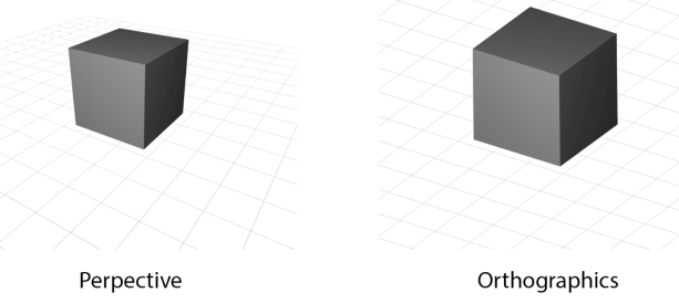
“Parallel projection”:
Parallel projection is basically the exact same as before, but instead of draw X and Y scaling into the center giving perspective effect, we just display the points on a much more honest position of where it is in 3D! basically:
Draw X = ( Point X - Camera X )
Draw Y = ( Point Y - Camera Y ) + ( ( Point Z - Camera Z ) / Depth Factor )
As you can see, this is much more simple. this means, lines that are indeed parallel will ACCURATELY be parallel in 2D too!
The depth factor is used to give the effect of the shapes being 3D. the more it is, the more the shape will be “compressed” in a 3D way. a depth factor of 1 will make the shapes look really “Distorted”, while a factor of something huge like “100000” will almost completely hide the top surfaces of the shape!
Rotation here, is also the same, just that it's more of rotating around a center point rather than a perception camera, as you're just seeing raw points projected to look like their original state as much as possible, and not actually perceived with an eye or camera.
“2.5D projection”:
as mentioned earlier, those projects sometimes are actually 3D. they are exactly the same as the “3D projection” from earlier, however not containing actual rotation around the point. this makes them lack some of 3D aspects, making people call them 2.5D projects. however, if your “2.5D” project was built upon 3D point data, then it indeed is an actual 3D calculation.
These projects are good for 3D scroller games or platformers that just dont rotate the camera at ALL, so even if the camera rotated a single degree to the left, that invalidates it being categorized as 2.5D, as it then includes actual rotation. however, fake rotation can be made, as you can “skew” the screen to the left or right, up or down, and make it look like it's rotating, which works for small angles, like 10-15 degrees, before starting to look off.
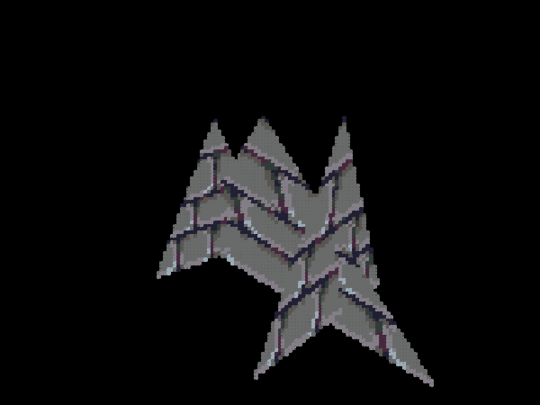
“Rasterization”
Rasterization, often working with Triangles or Quads, is used for more advanced and passionate projects. it uses a special screen that scratch does not provide, rendered with the Pen extension. The screen specializes in being made with individual pixels, that have a special attribute, other than the x, y, and color, which is the “z” attribute. this enables us to perfectly sort our shapes in 3D.
But how do we even draw them? and WHERE do we draw them?
we draw them using also specifically made blocks, that use specifically made LINE blocks, and those line blocks use specifically made PIXEL blocks, which draws a single pixel.
Rasterization tends to lag a lot due to the huge amount of pixels being drawn in a single frame, and that's why you're mostly gonna run a raster ONLY on turbowarp ( A scratch mod that speeds the code, but doesn't alter it's algorithms or code ) . but the code is still pure scratch, making it qualify as one of it's 3D projects method's.
We can now reach a conclusion that rasterization is just drawing 2D shapes on the screen with a special block, which you can make it yourself with enough experience. but now what?
WHERE do we draw those shapes, or more accurately, WHAT are the points where we will draw these shapes?
you said it, POINTS, we're back to 3D projection. whether you're using triangles, 2DTriangle: (a(x,y),b(x,y),c(x,y)), or Quad shapes, 2DQuad: (a(x,y),b(x,y),c(x,y),d(x,y)), you're always gonna need the “Draw x” and “Draw y” from earlier!
So now, instead of drawing a simple sprite or a line with your vertices, you will use your custom made screen to draw a shape BETWEEN them. this will give the illusion of actual 3D shapes in 3D, and not just simple lines or sprites. and since you made this custom screen, with lists you can actually get textures displaying on your quad / triangle, which is where things get exciting. you can also make points rotate around each other, making actual animations for characters or cars or buildings or anything you can imagine of!
the only problem is speed, so you will need LOADS of optimization, and knowledge on blocks to use and others to avoid!
“Raytracing”:
Raytracing is the only 3D method in this list that doesn't use 3D projection. Raytracing is the much more .. fascinating version of perceiving 3D objects.
With raytracing, you're actually diving deep into our understanding of our world, and challenging yourself with programming, with raytracing you're Really getting into how our eyes work, and how we can get a similar result with computers. with raytracing…. you're getting a free understanding of our world, and of the computer world
okay lets not get too excited, WHAT is raytracing? well, we first need to look at our own eyes, yep! with eyes, LIGHT is going from the source and bouncing off objects, then reaching our eyes. I just want you to imagine how many light rays there is right now, how INSANE that amount of light rays is, for only a few of them actually finding their way into our eyes. we can try to make a program like that with a computer, but that will be much more harder to simulate AND for something like scratch, it will indeed take too much time to even get a decent result..
But what if we aim for a simpler goal, instead, WE will be the source of those “rays”… so are we some kind of light? nope, its more like we are a scanning device that gets the information from the environment.
okay, lets remember “Rasterization” for a second, remember the special screen we had before? cool, we don't want to make it exactly like there, but it will be similar. we want to cover our scratch stage with special PEN DOTS, that will eventually cover all the (480x240) area. if you start to think about it, we can control each pixel to have certain color! a simple example would be setting the pen dots to have a random color, or a random brightness ( color is gray ), you will get a screen that looks like an old TV! we can also change the color, and so we will get a colorful lines that move all over our screen.. cool!
We realize after that, that we are just controlling the color of each pixel. What if, we think of it like this: we are gonna use our pixels to look at our world.
Each pixel will send a line that will keep moving till it collides with a certain object, and the color of that pixel will be the color of the surface it touched…!
this will form a screen, that looks like an actual perception of what you are trying to see!
We will need experience in certain topics to accomplish that:
Vectors > moving those special rays / lines.
Lists > Making the environment, cubes or special triangles or quads.
Variables > oh boy, you'll be making a lot of calculations.
Loops > you need to organize your loops to get the most with the least amount of steps.
Physics > for the camera and ray.
Lighting > general idea of light and RGB computer colors.
If you look at any raytracing project in scratch, you can easily recognize the most crucial parts, which are the screen loop, which sends rays, and the rays themselves.
Raytracers in scratch are mostly either ‘Voxel’ Raytracers, which use a special algorithm ( DDA ) to quickly find their path, or a ‘Sphere’ tracer, which uses rays as static lines that don't move and use math to detect if those lines intersected with the said so spheres.
A raytracer will allow you to simulate how the light works, as you can be much more free with the hard effects, and will be able to accomplish more. you can try making shadows, which are just the ray bouncing off the object toward a certain 3D point, and if it collides on the way, it indeed is in shadow.
You can also try reflection, which is another ray bouncing off the object, this time in certain angles, that will collide with the objects and mix the RGB of the old object with the new object, making it look like reflecting. a mirror will have the RGB mix factor up to 100%, while a dull object can have 15% for instance. something like metal would have 40% to 60%, and so on.
You can also have ambient occlusion, which is just a simple effect that's applied to objects when they are near each other, making them get darker. it looks Really pleasing and can make your scene look much more clean and realistic, and it's seen in games like minecraft, when you turn on smooth lighting.
Raytracing especially on scratch faces a big challenge, Performance. it's extremely slow, even on turbowarp, so if you see a 3D Raytracer working on a high resolution with a low fps on turbowarp, don't assume that it's slow. it's actually fast and optimized, but due to scratch's limitations, runs like that.
2D projects that just look 3D
What We explained earlier was real 3D that is projected or perceived in a way that can be then seen as 2D in the screen.. but what if it was a bit more different?
in Raycasting, or mode7, we are dealing with 2D points, 2D shapes, 2D rays, that have special TRICKS to look 3D!
Yep, you can even have heights, textures, and even Slopes, and it's all still 2D. My projects utilize this perhaps so much.
I genuinely believe that 2D raycasting is often overlooked due to the fact that it's simple. many 3D scratchers code it as their first “Demo” but move on. However, i believe that It has much potential, and you will realize how:
2D raycasting has many types, but here are the most popular:
“Tile raycasting” (similar to voxel raytracing, just 2D and much more simple, also uses the 2D version of DDA)
“Raylisting”
“Sprite raycasting” ( just… don't )
“SDF raycasting”
“Line Intersection raycasting” (My personal favorite.. I'm dying to explain this)
and finally,
“Mode7” ( lovely way to add depth to your raycaster, with floors and walls, and as I proved possible in my NFS:HP project, Smooth terrain )
So, what exactly should you use from above?
well, depends. is your project aiming for a simple game, with perhaps some height? use raylisting, which is a 2D raycaster that uses DDA and lists to store intersections. an example is Griffpatch's 3D maze.
is your game project aiming for Slopes, textures, speed, moving objects, better collisions and physics, surfaces, and much more? use LINE intersection raycasting.
both raycasters render with vertical lines to draw your “3D looking” illusion.
What is the difference though? well, a normal raycaster, like a sprite raycaster or a tile raycaster, or even a raylister, will use a point and keep moving it till it hits something.. and that's like pure torture for scratch, and the performance challenges lie exactly in the algorithm itself. a ray will have to perform a lot of calculations, just to get a single a single vertical line.
With Line intersection though, your ray isn't a point that moves. it's an infinitely long line that detects if something touches it instantly. and here you go, with a simple line intersection formula, you can have the first line as a “ray” and other as a “wall” . throw in some attributes for your 2D wall, like fake height, or textures, or both! you're gonna get some impressively fast results!
but then comes the biggest problem in performance, DRAWING the lines. you see, with normal raycasting, you get your walls sorted and ready because of the way you perceived them! with line intersection, nah, you can detect a wall that's a million light years away just as quick as one that's literary a foot away..
So this means, we need to use a special screen, just like in rasterization. now , we can sort, but this means performance was nerfed like crazy, now you need to run the project at low resolutions to have it look good.
even with this performance hit, you can still really run MUCH faster than normal raycasting, and even get more freedom. with enough engineering, you can get 3D slopes, and if that's too hard, you already have 2D slopes to work with, so much more scenes that can be made. my game's are often mistaken with rasterization because of how well this technology is in creating what looks like 3D, When indeed it is just 2D geometry!
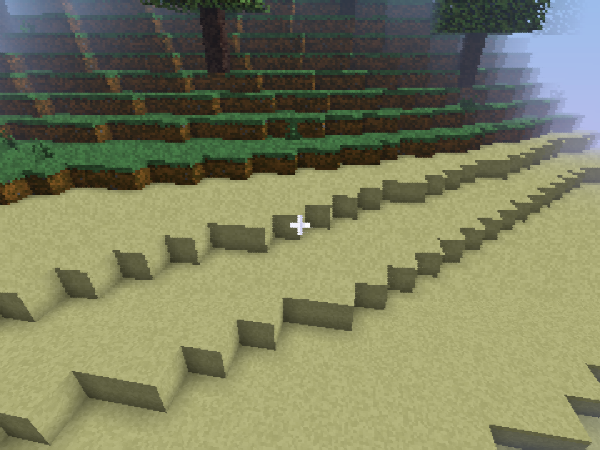
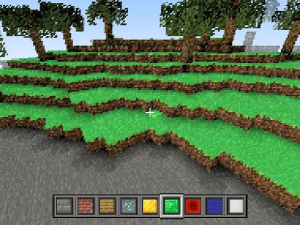
what about “Mode7”?
It's simply the Raycasting way to get 3D looking floors and walls. type mode7 in the scratch search or look at one of my projects. you'll always going to find a floor with a texture on it, and it looks just as 3D as your desk surface does. but if i told you it's just 2D that's been stretched in a certain way, would you believe it?
Mode7 sends rays just like a normal raycaster would, a point that moves by a vector. it's position is used to get the ( u, v ) coordinate of the texture you have saved in your list. this simply makes it find exactly where to display it. now, instead of drawing a vertical line like a normal raycaster, you draw horizontal lines, slowly covering the bottom sector of your scratch screen ( 0 to -180 ). this will give the illusion of actual 3D floor on from your perspective to the horizon. mode7 uses simple trigonometry vectors to and scales them as your ray gets closer to the horizon. this makes it look like you are indeed looking at 3D floor, not just a 2D stretched image!
HOW DO WE GET A DECENT LOOKING 3D ENGINE
Every 3D maker has their own way. I love combining 3 Methods in one project, that being Raster ( for complex models or moving objects, like a player ) Line segment raycasting ( for the environment ) and a mode7 ( for the floor ). this had enabled me to create fascinating PS1/ 3DS style games that impressed people. if you're an advanced scratcher, I'm sure you are capable of turning your thought's into a program. so calm down, understand 3D illusions, and translate those amazing ideas… into amazing projects
That's all my friends, would hugely appreciate if you followed me and shared your opinions on the topic below, if you have any questions, I'll make sure to answer them, peace!
INTRODUCTION
3D on scratch, or in general, has always been a controversial topic. we need to exactly define what “3D” we thrive to explain in this tutorial. Many projects tend to call themselves “3D”, But Are they? You see, if you dive deeper into this topic, EVERY 3D you see on your “2D” screen is just an illusion. even modern games, they are all 2D illusions that our brain is tricked into thinking that they're 3D. We are so used to 3D objects in real life that we just feel the depth in those 2D shapes that appear on the screen, making us feel like we indeed are looking at real 3D objects.
But how is that case with scratch? is scratch capable of making these illusions ?
Yep , scratch indeed is VERY capable of. In fact, you can create 3D illusions on flat 2D paper, and scratch, with it's lovely interactive stage, is no excepetion of that! We need to understand how to reach that illusion, and then we can actually start thinking right on how to start making our 3D project.
TYPES OF “3D” YOU CAN MAKE
you see, we reached a conclusion that anything “2D” on our screen that we can feel the depth of is indeed our “3D illusion”. We can then look more into the projects the community made. you'll find a variety of ways people tried to make that illusion.
Looking more into projects, you can categorize them into many different ways. for now, ill categorize them into 2 simple fields: “Static” and “Rendered”.
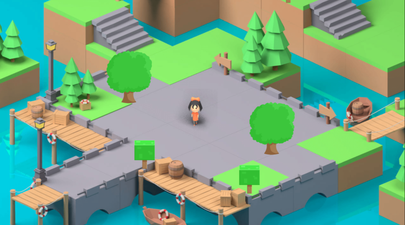
Static projects often tend to be still images, that have that “depth illusion” on them. our now “3D” player moves in special ways that makes it look indeed moving in 3D. More can be done, having special looking sprites that can work next to each other, think of it like putting Legos together, you can form a nice little isometric view, and that's it!
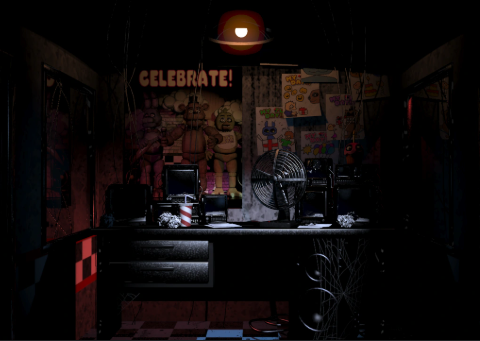
another “static” type of 3D you can find here is a room perspective, mostly a “1 point perspective”. here, users will use an image of a room, and make interactable sprites on the image, making it “feel” like you are in a 3D environment. a good example would be “FNAF” creations here in scratch.
But that is about how good as it gets! with certain amount of effects and polish, you can indeed get a decent project using this simple “3D” illusion, but some passionate people, thrive for more, and That's probably why YOU are here!
ACTUALLY RENDERED 3D PROJECTS
Now, what about “Rendered” 3D projects? we can define rendered as anything that scratch had generated. that could be with “Clones” or “Sprites”, or, the most powerful among them, “Pen” graphics. But how exactly do we even get there?
We need to deepen our understanding on how a Computer “Thinks” of 3D, and how WE do.
When an artist draws 3D, they have experience of drawing these objects, as well as them being human beings who interact with 3D on a daily basis, so our brains can easily imagine 3D objects, and with enough training, you can actually start drawing them!
but with computers, it doesn't really work that way. The computer is just a machine that's executing certain instructions in order, and therefore reaching our expected output.
So we need an “Algorithm” to draw our, as we said before, “3D” illusions which are 2D!!
you might have guessed it now, we're back to good ol' 2D scratch. that's how it's been all the way!
now, lets look at some popular algorithms that are used to get these 2D shapes.
“Raycasting”
“Raytracing”
“Rasterization”
“Parallel Projection”
“2.5D Projection”
“3D Projection”
“Mode7”
you might have been surprised by those names, and already got the chills of the long code that will take forever to make… right?
No worries, lets simplify things by sorting them into categories:
3D projects that Are 3D but are turned into 2D illusions:
“3D projection”
“Parallel projection”
Some “2.5D projection” projects
“Rasterization”
“Raytracing”
2D projects that just look 3D
“Raycasting”
Most “2.5D projection” projects
“Mode7”
Lets start simple, with actual 3D projects.
These projects are REALLY associated with math so much, as it's our key into reaching the illusion we need! Lets start with:
“3D projection”:
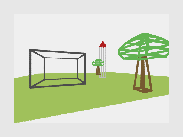
You might have encountered many 3D projects that have 2D sprites that just face you. you might also have encountered a project with a cube that looks like a “wireframe”, simply some pen lines connected between vertices on your screen. If you look more closely, you will find that both the CENTER and the VERTICES in those projects are points in 2D, with an X and Y. but that wasn't the case when the program first ran!
The program received those points as an X, Y, and Z!! So now you can figure out it's job, Mr. program, All you want to do is turn those 3D points into 2D!
But that's not enough, as we need a way to be able to tell the program where we are in the space! and that is what a “Camera” is for.
A Camera can be 3 Simple variables, simply (x, y, and z), and we can move it just like any 2D sprite, just changing the “y” axis into the “z” axis for normal movement, and going up and and down will just be your “y” position!
Okay, now we have a camera, a point, and now what? well, the program will take this point, and apply certain math to it using an FOV constant ( the field of view ), and You will return with 2 values, Draw x, and Draw y. Lovely!
but what exactly do we do to get those values? its just 1 calculation:
Draw X = ( Point X - Camera X ) * ( FOV / ( Point Z - Camera Z ) )
Draw Y = ( Point Y - Camera Y ) * ( FOV / ( Point Z - Camera Z ) )
with a quick look, you can notice that the Z dimension is Scaling the X and Y dimension, specifically into the Center of the project, as the larger the Z gets the Closer your point will get to the center. But that's not really it, as your project now lacks rotation!
So now, you want to apply a rotation matrix, More can be found on it in the web.
Your rotation matrix will rotate the point around the CAMERA, which will be centered in the middle of the world.
When you play the project, it will seem like you're actually going around the world, but what's really happening is that the WORLD is going around YOU instead.
You have 3 Axis to rotate around in 3D, all which are done with the same rotation formula. Your camera will require 3 More variables, Rotation on the x, y, and z.
Cool, now we have the point on the screen! what can we do with it? we can either use clones/ stamping sprites to draw 2D sprites on the screen that move and feel 3D, or we can go more further, creating more points and connecting between them to create simple shapes!
“Parallel projection”:
Parallel projection is basically the exact same as before, but instead of draw X and Y scaling into the center giving perspective effect, we just display the points on a much more honest position of where it is in 3D! basically:
Draw X = ( Point X - Camera X )
Draw Y = ( Point Y - Camera Y ) + ( ( Point Z - Camera Z ) / Depth Factor )
As you can see, this is much more simple. this means, lines that are indeed parallel will ACCURATELY be parallel in 2D too!
The depth factor is used to give the effect of the shapes being 3D. the more it is, the more the shape will be “compressed” in a 3D way. a depth factor of 1 will make the shapes look really “Distorted”, while a factor of something huge like “100000” will almost completely hide the top surfaces of the shape!
Rotation here, is also the same, just that it's more of rotating around a center point rather than a perception camera, as you're just seeing raw points projected to look like their original state as much as possible, and not actually perceived with an eye or camera.
“2.5D projection”:
as mentioned earlier, those projects sometimes are actually 3D. they are exactly the same as the “3D projection” from earlier, however not containing actual rotation around the point. this makes them lack some of 3D aspects, making people call them 2.5D projects. however, if your “2.5D” project was built upon 3D point data, then it indeed is an actual 3D calculation.
These projects are good for 3D scroller games or platformers that just dont rotate the camera at ALL, so even if the camera rotated a single degree to the left, that invalidates it being categorized as 2.5D, as it then includes actual rotation. however, fake rotation can be made, as you can “skew” the screen to the left or right, up or down, and make it look like it's rotating, which works for small angles, like 10-15 degrees, before starting to look off.
“Rasterization”
Rasterization, often working with Triangles or Quads, is used for more advanced and passionate projects. it uses a special screen that scratch does not provide, rendered with the Pen extension. The screen specializes in being made with individual pixels, that have a special attribute, other than the x, y, and color, which is the “z” attribute. this enables us to perfectly sort our shapes in 3D.
But how do we even draw them? and WHERE do we draw them?
we draw them using also specifically made blocks, that use specifically made LINE blocks, and those line blocks use specifically made PIXEL blocks, which draws a single pixel.
Rasterization tends to lag a lot due to the huge amount of pixels being drawn in a single frame, and that's why you're mostly gonna run a raster ONLY on turbowarp ( A scratch mod that speeds the code, but doesn't alter it's algorithms or code ) . but the code is still pure scratch, making it qualify as one of it's 3D projects method's.
We can now reach a conclusion that rasterization is just drawing 2D shapes on the screen with a special block, which you can make it yourself with enough experience. but now what?
WHERE do we draw those shapes, or more accurately, WHAT are the points where we will draw these shapes?
you said it, POINTS, we're back to 3D projection. whether you're using triangles, 2DTriangle: (a(x,y),b(x,y),c(x,y)), or Quad shapes, 2DQuad: (a(x,y),b(x,y),c(x,y),d(x,y)), you're always gonna need the “Draw x” and “Draw y” from earlier!
So now, instead of drawing a simple sprite or a line with your vertices, you will use your custom made screen to draw a shape BETWEEN them. this will give the illusion of actual 3D shapes in 3D, and not just simple lines or sprites. and since you made this custom screen, with lists you can actually get textures displaying on your quad / triangle, which is where things get exciting. you can also make points rotate around each other, making actual animations for characters or cars or buildings or anything you can imagine of!
the only problem is speed, so you will need LOADS of optimization, and knowledge on blocks to use and others to avoid!
“Raytracing”:
Raytracing is the only 3D method in this list that doesn't use 3D projection. Raytracing is the much more .. fascinating version of perceiving 3D objects.
With raytracing, you're actually diving deep into our understanding of our world, and challenging yourself with programming, with raytracing you're Really getting into how our eyes work, and how we can get a similar result with computers. with raytracing…. you're getting a free understanding of our world, and of the computer world
okay lets not get too excited, WHAT is raytracing? well, we first need to look at our own eyes, yep! with eyes, LIGHT is going from the source and bouncing off objects, then reaching our eyes. I just want you to imagine how many light rays there is right now, how INSANE that amount of light rays is, for only a few of them actually finding their way into our eyes. we can try to make a program like that with a computer, but that will be much more harder to simulate AND for something like scratch, it will indeed take too much time to even get a decent result..
But what if we aim for a simpler goal, instead, WE will be the source of those “rays”… so are we some kind of light? nope, its more like we are a scanning device that gets the information from the environment.
okay, lets remember “Rasterization” for a second, remember the special screen we had before? cool, we don't want to make it exactly like there, but it will be similar. we want to cover our scratch stage with special PEN DOTS, that will eventually cover all the (480x240) area. if you start to think about it, we can control each pixel to have certain color! a simple example would be setting the pen dots to have a random color, or a random brightness ( color is gray ), you will get a screen that looks like an old TV! we can also change the color, and so we will get a colorful lines that move all over our screen.. cool!
We realize after that, that we are just controlling the color of each pixel. What if, we think of it like this: we are gonna use our pixels to look at our world.
Each pixel will send a line that will keep moving till it collides with a certain object, and the color of that pixel will be the color of the surface it touched…!
this will form a screen, that looks like an actual perception of what you are trying to see!
We will need experience in certain topics to accomplish that:
Vectors > moving those special rays / lines.
Lists > Making the environment, cubes or special triangles or quads.
Variables > oh boy, you'll be making a lot of calculations.
Loops > you need to organize your loops to get the most with the least amount of steps.
Physics > for the camera and ray.
Lighting > general idea of light and RGB computer colors.
If you look at any raytracing project in scratch, you can easily recognize the most crucial parts, which are the screen loop, which sends rays, and the rays themselves.
Raytracers in scratch are mostly either ‘Voxel’ Raytracers, which use a special algorithm ( DDA ) to quickly find their path, or a ‘Sphere’ tracer, which uses rays as static lines that don't move and use math to detect if those lines intersected with the said so spheres.
A raytracer will allow you to simulate how the light works, as you can be much more free with the hard effects, and will be able to accomplish more. you can try making shadows, which are just the ray bouncing off the object toward a certain 3D point, and if it collides on the way, it indeed is in shadow.
You can also try reflection, which is another ray bouncing off the object, this time in certain angles, that will collide with the objects and mix the RGB of the old object with the new object, making it look like reflecting. a mirror will have the RGB mix factor up to 100%, while a dull object can have 15% for instance. something like metal would have 40% to 60%, and so on.
You can also have ambient occlusion, which is just a simple effect that's applied to objects when they are near each other, making them get darker. it looks Really pleasing and can make your scene look much more clean and realistic, and it's seen in games like minecraft, when you turn on smooth lighting.
Raytracing especially on scratch faces a big challenge, Performance. it's extremely slow, even on turbowarp, so if you see a 3D Raytracer working on a high resolution with a low fps on turbowarp, don't assume that it's slow. it's actually fast and optimized, but due to scratch's limitations, runs like that.
2D projects that just look 3D
What We explained earlier was real 3D that is projected or perceived in a way that can be then seen as 2D in the screen.. but what if it was a bit more different?
in Raycasting, or mode7, we are dealing with 2D points, 2D shapes, 2D rays, that have special TRICKS to look 3D!
Yep, you can even have heights, textures, and even Slopes, and it's all still 2D. My projects utilize this perhaps so much.
I genuinely believe that 2D raycasting is often overlooked due to the fact that it's simple. many 3D scratchers code it as their first “Demo” but move on. However, i believe that It has much potential, and you will realize how:
2D raycasting has many types, but here are the most popular:
“Tile raycasting” (similar to voxel raytracing, just 2D and much more simple, also uses the 2D version of DDA)
“Raylisting”
“Sprite raycasting” ( just… don't )
“SDF raycasting”
“Line Intersection raycasting” (My personal favorite.. I'm dying to explain this)
and finally,
“Mode7” ( lovely way to add depth to your raycaster, with floors and walls, and as I proved possible in my NFS:HP project, Smooth terrain )
So, what exactly should you use from above?
well, depends. is your project aiming for a simple game, with perhaps some height? use raylisting, which is a 2D raycaster that uses DDA and lists to store intersections. an example is Griffpatch's 3D maze.
is your game project aiming for Slopes, textures, speed, moving objects, better collisions and physics, surfaces, and much more? use LINE intersection raycasting.
both raycasters render with vertical lines to draw your “3D looking” illusion.
What is the difference though? well, a normal raycaster, like a sprite raycaster or a tile raycaster, or even a raylister, will use a point and keep moving it till it hits something.. and that's like pure torture for scratch, and the performance challenges lie exactly in the algorithm itself. a ray will have to perform a lot of calculations, just to get a single a single vertical line.
With Line intersection though, your ray isn't a point that moves. it's an infinitely long line that detects if something touches it instantly. and here you go, with a simple line intersection formula, you can have the first line as a “ray” and other as a “wall” . throw in some attributes for your 2D wall, like fake height, or textures, or both! you're gonna get some impressively fast results!
but then comes the biggest problem in performance, DRAWING the lines. you see, with normal raycasting, you get your walls sorted and ready because of the way you perceived them! with line intersection, nah, you can detect a wall that's a million light years away just as quick as one that's literary a foot away..
So this means, we need to use a special screen, just like in rasterization. now , we can sort, but this means performance was nerfed like crazy, now you need to run the project at low resolutions to have it look good.
even with this performance hit, you can still really run MUCH faster than normal raycasting, and even get more freedom. with enough engineering, you can get 3D slopes, and if that's too hard, you already have 2D slopes to work with, so much more scenes that can be made. my game's are often mistaken with rasterization because of how well this technology is in creating what looks like 3D, When indeed it is just 2D geometry!
what about “Mode7”?
It's simply the Raycasting way to get 3D looking floors and walls. type mode7 in the scratch search or look at one of my projects. you'll always going to find a floor with a texture on it, and it looks just as 3D as your desk surface does. but if i told you it's just 2D that's been stretched in a certain way, would you believe it?
Mode7 sends rays just like a normal raycaster would, a point that moves by a vector. it's position is used to get the ( u, v ) coordinate of the texture you have saved in your list. this simply makes it find exactly where to display it. now, instead of drawing a vertical line like a normal raycaster, you draw horizontal lines, slowly covering the bottom sector of your scratch screen ( 0 to -180 ). this will give the illusion of actual 3D floor on from your perspective to the horizon. mode7 uses simple trigonometry vectors to and scales them as your ray gets closer to the horizon. this makes it look like you are indeed looking at 3D floor, not just a 2D stretched image!
HOW DO WE GET A DECENT LOOKING 3D ENGINE
Every 3D maker has their own way. I love combining 3 Methods in one project, that being Raster ( for complex models or moving objects, like a player ) Line segment raycasting ( for the environment ) and a mode7 ( for the floor ). this had enabled me to create fascinating PS1/ 3DS style games that impressed people. if you're an advanced scratcher, I'm sure you are capable of turning your thought's into a program. so calm down, understand 3D illusions, and translate those amazing ideas… into amazing projects
That's all my friends, would hugely appreciate if you followed me and shared your opinions on the topic below, if you have any questions, I'll make sure to answer them, peace!
Last edited by GL00B (May 27, 2025 20:27:05)
- benjaminwillard
-
 Scratcher
53 posts
3D on scratch, And how it's professionally accomplished
This is awesome! I never heard of the 2D raycasting: Mode7 method! Your projects are amazing, and I want to thank you for writing a whole post about the different methods, and types of 3D projects on scratch. Truly impressive work!
- scratchcode1_2_3
-
 Scratcher
1000+ posts
3D on scratch, And how it's professionally accomplished
Wow, I was just playing your games yesterday! Can’t believe you made a post about it!
- kittygamer8997
-
 Scratcher
69 posts
3D on scratch, And how it's professionally accomplished
I always wondered how I could do something like line intersection raycasting because I don't know how that works. how does it detect collisions like that? I only know step by step or DDA. how does it know where the collision is??? please teach me or give me something to tell me how it works.


- zenithIsReal
-
 Scratcher
44 posts
3D on scratch, And how it's professionally accomplished
Thank you for teaching us your ways lol
- GL00B
-
Scratcher
89 posts
3D on scratch, And how it's professionally accomplished
I always wondered how I could do something like line intersection raycasting because I don't know how that works. how does it detect collisions like that? I only know step by step or DDA. how does it know where the collision is??? please teach me or give me something to tell me how it works.
Glad you're interested! Since you know how to code a DDA raycaster, I'm really sure that you use vectors for it. Your Line intersection raycaster will have the same code as your normal DDA raycaster up until the actual loop. there, you will be checking a list that has your map data, cycling through it. you won't be using a voxel list, or a tile list, nope, just a list that has your data in certain packets that you can cycle through by the length of the packet. so simply:
( Wall_index * ( Packet_length ) + Wall_attribute [ this is where you store the x1,y1,z2,texture,height,anything you can think of. ) of
then you will use a line intersection formula, to find the intersection between 2 lines. one will be your ray, and the other will be the wall in the list. you cycle through the list and you will have checked intersection with the rays. the formula i use is this one :
https://www.youtube.com/watch?v=bvlIYX9cgls
You will use the alpha and beta to determine the Distance and the U coordinate in the texture of that wall. Thats all
**** note ****
you will realise the walls are NOT sorted, so you will need to use a z buffer, which will limit the y axis's resolution too. it will also greatly reduce the performance, so code it right and avoid extra calculations as much as possible!
- The-Locust
-
 Scratcher
3 posts
3D on scratch, And how it's professionally accomplished
3D raytracing is confusing, and the code is. Please don't get me on there
- GL00B
-
Scratcher
89 posts
3D on scratch, And how it's professionally accomplished
3D raytracing is confusing, and the code is. Please don't get me on therethis topic is for advanced scratch, please do not get here as a “new scratcher” and start complaining about raytracing or whatever being confusing to you, as it's Fascinating to others who try to learn it
- L15mar
-
 Scratcher
10 posts
3D on scratch, And how it's professionally accomplished
I dont want to use turbowarp for some simple raycasting.
But you can use something like this:
But you can use something like this:
define Render
Use some 3D engine for this but i has an engine for you
define Go to X:(X) Y:(Y) Z:(Z)
go to x: ((FL) * ((X) / (Z))) y: ((FL) * ((Y) / (Z)))
- GL00B
-
Scratcher
89 posts
3D on scratch, And how it's professionally accomplished
I dont want to use turbowarp for some simple raycasting.
But you can use something like this:
define Render
Use some 3D engine for this but i has an engine for you
define Go to X:(X) Y:(Y) Z:(Z)
go to x: ((FL) * ((X) / (Z))) y: ((FL) * ((Y) / (Z)))
Did you just skip the explanation? i literary mentioned this..
- shadow8737
-
 Scratcher
500+ posts
3D on scratch, And how it's professionally accomplished
3D raytracing is confusing, and the code is. Please don't get me on thereBro you have 0 posts
- PaxtonPenguin
-
 Scratcher
100+ posts
3D on scratch, And how it's professionally accomplished
Should i sticky this?
- GL00B
-
Scratcher
89 posts
3D on scratch, And how it's professionally accomplished
Should i sticky this?Yes, would appreciate it!
- _-SuperMarioGalaxy-_
-
 Scratcher
9 posts
3D on scratch, And how it's professionally accomplished
yo this is sick
- kittygamer8997
-
Scratcher
69 posts
3D on scratch, And how it's professionally accomplished
Too much stuff. i am very very very confused and how would you even make the map?I always wondered how I could do something like line intersection raycasting because I don't know how that works. how does it detect collisions like that? I only know step by step or DDA. how does it know where the collision is??? please teach me or give me something to tell me how it works.
Glad you're interested! Since you know how to code a DDA raycaster, I'm really sure that you use vectors for it. Your Line intersection raycaster will have the same code as your normal DDA raycaster up until the actual loop. there, you will be checking a list that has your map data, cycling through it. you won't be using a voxel list, or a tile list, nope, just a list that has your data in certain packets that you can cycle through by the length of the packet. so simply:
( Wall_index * ( Packet_length ) + Wall_attribute [ this is where you store the x1,y1,z2,texture,height,anything you can think of. ) of
then you will use a line intersection formula, to find the intersection between 2 lines. one will be your ray, and the other will be the wall in the list. you cycle through the list and you will have checked intersection with the rays. the formula i use is this one :
https://www.youtube.com/watch?v=bvlIYX9cgls
You will use the alpha and beta to determine the Distance and the U coordinate in the texture of that wall. Thats all
**** note ****
you will realise the walls are NOT sorted, so you will need to use a z buffer, which will limit the y axis's resolution too. it will also greatly reduce the performance, so code it right and avoid extra calculations as much as possible!
- magicsponge321
-
 Scratcher
100+ posts
3D on scratch, And how it's professionally accomplished
Hey GL00B, I hope you respond to this, I just wanted to say I love your projects and hope on being like you someday.
- GL00B
-
Scratcher
89 posts
3D on scratch, And how it's professionally accomplished
Hey GL00B, I hope you respond to this, I just wanted to say I love your projects and hope on being like you someday.Thanks
any questions on 3D in general? would love to help
- GL00B
-
Scratcher
89 posts
3D on scratch, And how it's professionally accomplished
Too much stuff. i am very very very confused and how would you even make the map?I always wondered how I could do something like line intersection raycasting because I don't know how that works. how does it detect collisions like that? I only know step by step or DDA. how does it know where the collision is??? please teach me or give me something to tell me how it works.
Glad you're interested! Since you know how to code a DDA raycaster, I'm really sure that you use vectors for it. Your Line intersection raycaster will have the same code as your normal DDA raycaster up until the actual loop. there, you will be checking a list that has your map data, cycling through it. you won't be using a voxel list, or a tile list, nope, just a list that has your data in certain packets that you can cycle through by the length of the packet. so simply:
( Wall_index * ( Packet_length ) + Wall_attribute [ this is where you store the x1,y1,z2,texture,height,anything you can think of. ) of
then you will use a line intersection formula, to find the intersection between 2 lines. one will be your ray, and the other will be the wall in the list. you cycle through the list and you will have checked intersection with the rays. the formula i use is this one :
https://www.youtube.com/watch?v=bvlIYX9cgls
You will use the alpha and beta to determine the Distance and the U coordinate in the texture of that wall. Thats all
**** note ****
you will realise the walls are NOT sorted, so you will need to use a z buffer, which will limit the y axis's resolution too. it will also greatly reduce the performance, so code it right and avoid extra calculations as much as possible!
Okay, lets simplify it. imagine the ray in a normal raycaster as a bullet that keeps moving till it hits something. right?
well, in our line segment raycaster, there is no bullet. there is just a laser beam, that instantly shows!
this laser beam checks if any lines are touching it. forget about making the map now, just tell me, is this clear? you are not moving till you hit a wall, you already hit the wall ever since the “beam” spawned, which is just a really long line that starts at your camera's position and it's end is a point that's equal to your vector + camera position.
- Discussion Forums
- » Advanced Topics
- » 3D on scratch, And how it's professionally accomplished